How to Use 74HC93: Examples, Pinouts, and Specs

Introduction
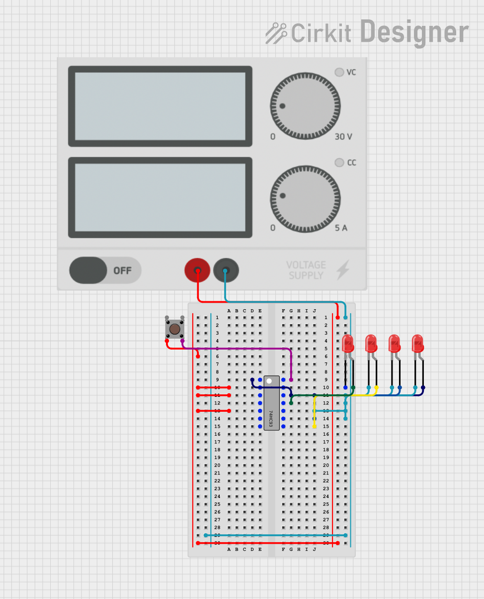
The 74HC93 is an integrated circuit that functions as a 4-bit binary ripple counter. It is part of the 74HC series, which are high-speed CMOS devices. The counter advances on the negative-going edge of the clock pulse and can be reset by a high level on the reset line. This component is widely used in digital electronics for counting purposes, such as in frequency dividers, timers, and other sequential logic applications.
Explore Projects Built with 74HC93


Explore Projects Built with 74HC93
Technical Specifications
Key Technical Details
- Supply Voltage (Vcc): 2.0V to 6.0V
- Input Voltage (Vin): -0.5V to Vcc + 0.5V
- Output Voltage (Vout): -0.5V to Vcc + 0.5V
- Clock Frequency (fclk): 0 to 70 MHz (varies with Vcc)
- Operating Temperature: -40°C to +125°C
- Propagation Delay: Varies with Vcc, input transition rise and fall time
Pin Configuration and Descriptions
| Pin Number | Name | Description |
|---|---|---|
| 1 | Q0 | First bit of the counter (LSB) |
| 2 | Q1 | Second bit of the counter |
| 3 | Q2 | Third bit of the counter |
| 4 | Q3 | Fourth bit of the counter (MSB) |
| 5 | MR1 | Master reset input (active HIGH) |
| 6 | MR2 | Master reset input (active HIGH) |
| 7 | GND | Ground (0V) |
| 8 | Vcc | Positive supply voltage |
| 9 | CP1 | Clock pulse input for Q0 and Q1 |
| 10 | CP0 | Clock pulse input for Q2 and Q3 |
| 11 | NC | No connection (leave open or can be used for PCB tracking) |
| 12 | NC | No connection (leave open or can be used for PCB tracking) |
| 13 | NC | No connection (leave open or can be used for PCB tracking) |
| 14 | NC | No connection (leave open or can be used for PCB tracking) |
Usage Instructions
How to Use the 74HC93 in a Circuit
- Power Supply Connection: Connect the Vcc pin to a positive supply voltage within the specified range and the GND pin to the ground of the circuit.
- Clock Inputs: Apply a clock signal to CP0 and CP1 pins to drive the counter. Ensure that the frequency of the clock does not exceed the maximum frequency rating.
- Master Reset: To reset the counter, apply a high level to either MR1 or MR2. Both MR1 and MR2 can be connected together for a single reset control if desired.
- Output Connection: Connect the Q0, Q1, Q2, and Q3 pins to the subsequent stages of your digital circuit as required.
Important Considerations and Best Practices
- Ensure that the input voltage levels do not exceed the supply voltage to prevent damage.
- Decouple the power supply with a 0.1 µF capacitor close to the Vcc pin to filter out noise.
- Avoid floating inputs by connecting unused inputs to the ground or Vcc as appropriate.
- Use pull-up or pull-down resistors if inputs are driven by mechanical switches to ensure defined logic levels.
Troubleshooting and FAQs
Common Issues
- Counter Not Advancing: Verify that the clock signal is within the specified frequency range and that the clock pulses are clean without excessive noise.
- Unexpected Resets: Check for noise on the master reset lines or ensure that they are not inadvertently being activated.
- Glitches on Outputs: Ensure that the power supply is stable and well-decoupled. Also, check for proper grounding.
Solutions and Tips for Troubleshooting
- If the counter is not advancing, check the clock input pins for proper signal integrity.
- For unexpected resets, ensure that the master reset pins are not picking up stray signals; consider using a pull-down resistor.
- To address glitches, verify the decoupling capacitors are in place and that there is a low-impedance path to ground.
FAQs
Q: Can the 74HC93 be used with an Arduino? A: Yes, the 74HC93 can be interfaced with an Arduino, provided the operating voltage levels are compatible.
Q: What is the maximum count of the 74HC93? A: The 74HC93 can count up to 15 in binary (1111).
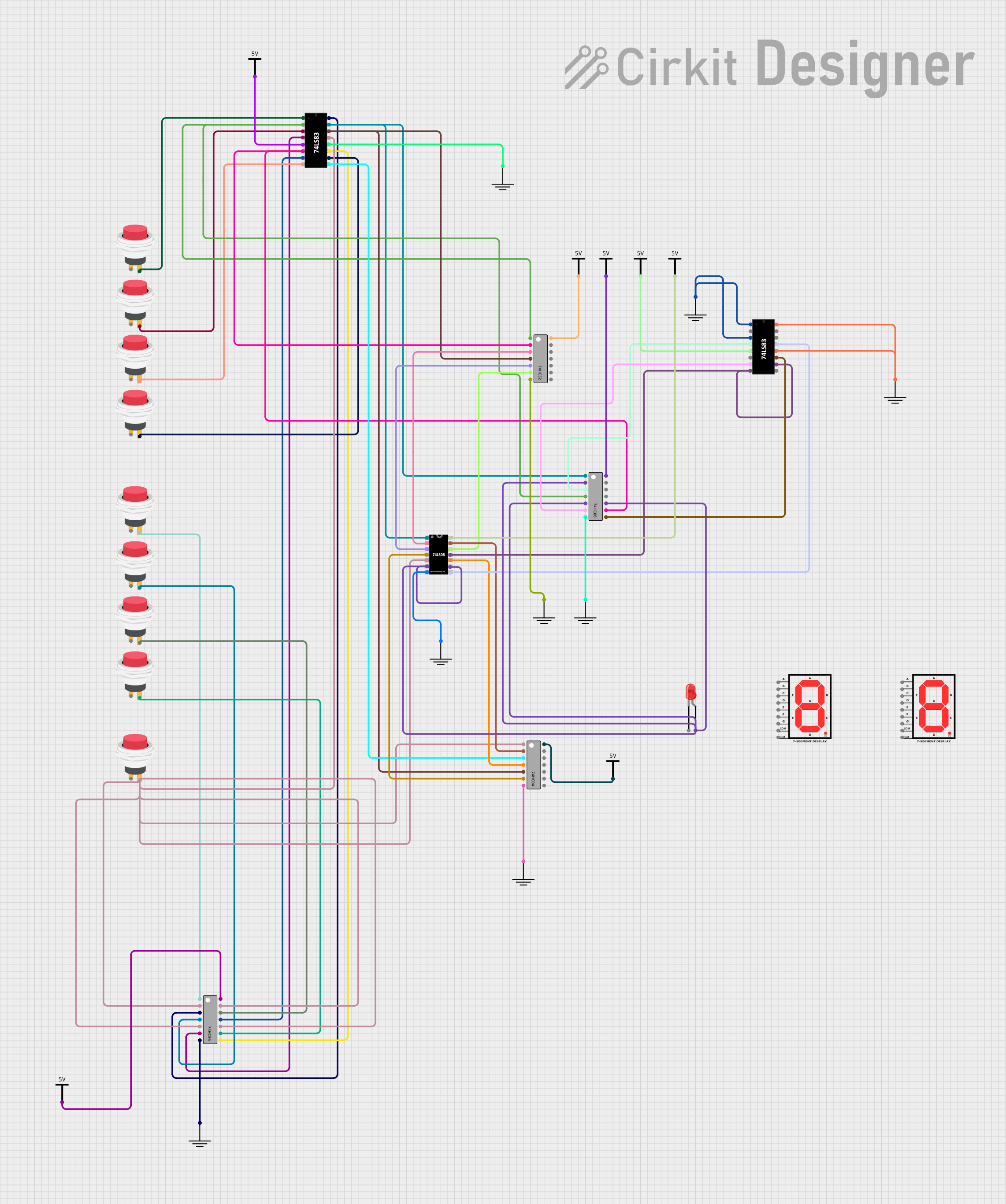
Q: How can I cascade multiple 74HC93 counters? A: You can cascade them by connecting the Q3 output of one counter to the clock input of the next counter.
Q: Is it necessary to use both master reset inputs? A: No, you can use either MR1 or MR2 to reset the counter. Connecting both to a single reset switch is also common.
Example Code for Arduino UNO
// Example code to interface 74HC93 with Arduino UNO

const int clockPin = 5; // Connect to CP0 or CP1
const int resetPin = 6; // Connect to MR1 or MR2

void setup() {
  pinMode(clockPin, OUTPUT);
  pinMode(resetPin, OUTPUT);
  // Start with the counter reset
  digitalWrite(resetPin, HIGH);
  delay(10);
  digitalWrite(resetPin, LOW);
}

void loop() {
  // Generate a clock pulse
  digitalWrite(clockPin, HIGH);
  delayMicroseconds(10); // Short pulse
  digitalWrite(clockPin, LOW);
  delay(1000); // Wait for 1 second
}
This example demonstrates how to generate clock pulses to increment the counter and how to reset the counter using an Arduino UNO. The clock pulse width and delay between pulses can be adjusted based on the specific application requirements.