Cirkit Designer
Your all-in-one circuit design IDE
Home /
Component Documentation
How to Use Adafruit Airlift Bitsy Add-On: Examples, Pinouts, and Specs
Introduction
The Adafruit Airlift Bitsy Add-On is a compact Wi-Fi co-processor module that brings wireless connectivity to Adafruit Feather boards. It leverages the capabilities of the ESP32, a powerful SoC with integrated Wi-Fi and Bluetooth functionalities. This add-on is particularly useful for Internet of Things (IoT) projects, enabling devices to communicate wirelessly for data transfer, remote monitoring, and control applications.
Explore Projects Built with Adafruit Airlift Bitsy Add-On
Battery-Powered Smart Sensor Hub with Adafruit QT Py RP2040

This circuit features an Adafruit QT Py RP2040 microcontroller interfaced with an APDS9960 proximity sensor, an MPU6050 accelerometer and gyroscope, and an OLED display via I2C communication. It also includes a buzzer controlled by the microcontroller and is powered by a 3.7V LiPo battery with a toggle switch for power control.
Battery-Powered Smart Light with Proximity Sensor and OLED Display using Adafruit QT Py RP2040

This circuit is a portable, battery-powered system featuring an Adafruit QT Py RP2040 microcontroller that interfaces with an OLED display, a proximity sensor, an accelerometer, and an RGB LED strip. The system is powered by a lithium-ion battery with a step-up boost converter to provide 5V for the LED strip, and it includes a toggle switch for power control. The microcontroller communicates with the sensors and display via I2C.
Adafruit MPU6050 and VL6180X Sensor Interface with Servo Control

This circuit features an Adafruit QT Py microcontroller interfaced with an Adafruit MPU6050 6-axis accelerometer/gyroscope and an Adafruit VL6180X Time of Flight (ToF) distance sensor, both connected via I2C communication. The QT Py also controls a Servomotor SG90, likely for physical actuation based on sensor inputs. The embedded code initializes the sensors, reads their data, and outputs the readings to a serial monitor, with the potential for motion control based on the sensor feedback.
Battery-Powered Sensor Hub with Adafruit QT Py RP2040 and OLED Display

This circuit features an Adafruit QT Py RP2040 microcontroller interfacing with an MPU-6050 accelerometer, an Adafruit APDS-9960 sensor, and a 0.96" OLED display via I2C communication. It is powered by a 3.7V LiPo battery and includes a green LED with a current-limiting resistor connected to an analog pin of the microcontroller.
Explore Projects Built with Adafruit Airlift Bitsy Add-On
Battery-Powered Smart Sensor Hub with Adafruit QT Py RP2040
This circuit features an Adafruit QT Py RP2040 microcontroller interfaced with an APDS9960 proximity sensor, an MPU6050 accelerometer and gyroscope, and an OLED display via I2C communication. It also includes a buzzer controlled by the microcontroller and is powered by a 3.7V LiPo battery with a toggle switch for power control.
Battery-Powered Smart Light with Proximity Sensor and OLED Display using Adafruit QT Py RP2040
This circuit is a portable, battery-powered system featuring an Adafruit QT Py RP2040 microcontroller that interfaces with an OLED display, a proximity sensor, an accelerometer, and an RGB LED strip. The system is powered by a lithium-ion battery with a step-up boost converter to provide 5V for the LED strip, and it includes a toggle switch for power control. The microcontroller communicates with the sensors and display via I2C.
Adafruit MPU6050 and VL6180X Sensor Interface with Servo Control
This circuit features an Adafruit QT Py microcontroller interfaced with an Adafruit MPU6050 6-axis accelerometer/gyroscope and an Adafruit VL6180X Time of Flight (ToF) distance sensor, both connected via I2C communication. The QT Py also controls a Servomotor SG90, likely for physical actuation based on sensor inputs. The embedded code initializes the sensors, reads their data, and outputs the readings to a serial monitor, with the potential for motion control based on the sensor feedback.
Battery-Powered Sensor Hub with Adafruit QT Py RP2040 and OLED Display
This circuit features an Adafruit QT Py RP2040 microcontroller interfacing with an MPU-6050 accelerometer, an Adafruit APDS-9960 sensor, and a 0.96" OLED display via I2C communication. It is powered by a 3.7V LiPo battery and includes a green LED with a current-limiting resistor connected to an analog pin of the microcontroller.
Common Applications and Use Cases
- IoT devices
- Remote sensors
- Wireless data logging
- Home automation
- Remote control for robotics
- Wearable electronics
Technical Specifications
Key Technical Details
- Wi-Fi Chipset: ESP32
- Network Protocols: 802.11b/g/n
- Bluetooth: Classic and BLE
- Operating Voltage: 3.3V
- Logic Levels: 3.3V (compatible with 5V logic with level shifting)
- Current Consumption: ~10 mA (idle), up to 250 mA (transmit)
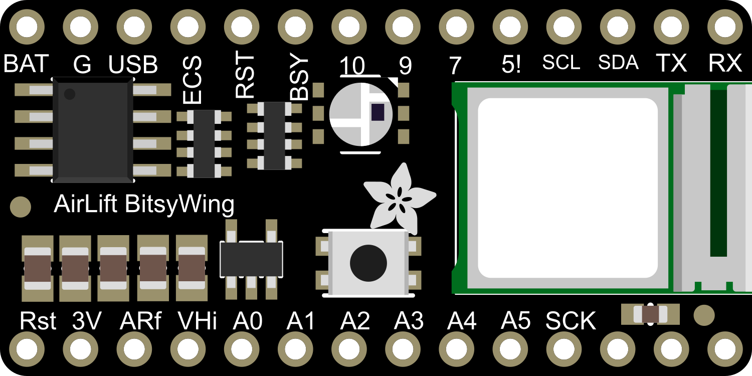
Pin Configuration and Descriptions
| Pin Number | Name | Description |
|---|---|---|
| 1 | GND | Ground connection |
| 2 | 3V | 3.3V power supply input |
| 3 | EN | Enable pin for the module |
| 4 | IO0 | Used for entering flashing mode |
| 5 | TX | UART transmit pin |
| 6 | RX | UART receive pin |
| 7 | SCK | SPI clock |
| 8 | MISO | SPI Master In Slave Out |
| 9 | MOSI | SPI Master Out Slave In |
| 10 | CS | SPI chip select |
Usage Instructions
How to Use the Component in a Circuit
- Power Supply: Connect the 3V pin to a 3.3V power source and GND to the ground.
- Enable Pin: Connect the EN pin to 3.3V to enable the module.
- SPI Communication: Connect SCK, MISO, MOSI, and CS to the corresponding SPI pins on your Feather board.
- UART Communication: Optionally, connect TX and RX for UART communication if required by your application.
Important Considerations and Best Practices
- Ensure that the power supply is stable and can provide sufficient current for both the Feather board and the Airlift module.
- Use proper decoupling capacitors close to the power pins to minimize noise.
- When using SPI communication, ensure that the SPI bus is not shared with other devices that may interfere with the Wi-Fi module's operation.
- For UART communication, ensure that the baud rate is correctly set to match the module's default or configured rate.
- Always disconnect the module from power before making or changing connections to prevent damage.
Troubleshooting and FAQs
Common Issues Users Might Face
- Module Does Not Power On: Check the power connections and ensure the EN pin is connected to 3.3V.
- No Wi-Fi Connection: Verify that the antenna is properly connected and that the Wi-Fi credentials are correctly set in your code.
- Intermittent Connectivity: Ensure that the power supply can handle peak current draws and that there is no significant voltage drop.
Solutions and Tips for Troubleshooting
- Double-check wiring against the pin configuration table.
- Use serial output to debug and check for error messages or status codes.
- Reset the module by toggling the EN pin if it becomes unresponsive.
- Update the firmware of the ESP32 module if persistent issues occur.
Relevant Arduino Code Example
#include <WiFi.h>

// Replace with your network credentials
const char* ssid = "your_SSID";
const char* password = "your_PASSWORD";

void setup() {
  // Initialize serial communication for debugging
  Serial.begin(115200);

  // Start the Wi-Fi connection process
  WiFi.begin(ssid, password);

  // Wait for connection
  while (WiFi.status() != WL_CONNECTED) {
    delay(500);
    Serial.print(".");
  }

  // Once connected, print the IP address
  Serial.println("");
  Serial.println("WiFi connected.");
  Serial.println("IP address: ");
  Serial.println(WiFi.localIP());
}

void loop() {
  // Your main code would go here
}
Remember to keep the code comments concise and within the 80 character line length limit. This example demonstrates how to connect the Adafruit Airlift Bitsy Add-On to a Wi-Fi network using an Arduino sketch.