Cirkit Designer
Your all-in-one circuit design IDE
Home /
Component Documentation
How to Use MSPM0G3507: Examples, Pinouts, and Specs
Introduction
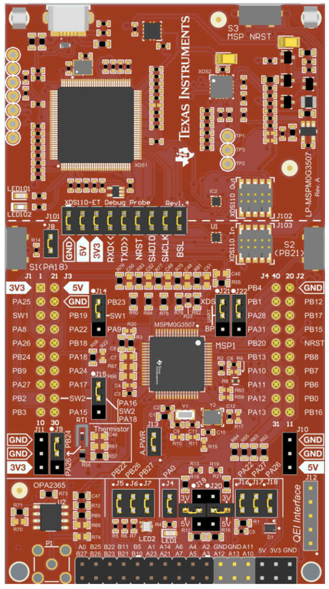
The MSPM0G3507 is a microcontroller from Texas Instruments, featuring an Arm Cortex-M0+ core. It is designed for low-power and cost-sensitive applications, making it ideal for a wide range of embedded systems. The microcontroller includes various peripherals such as Analog-to-Digital Converters (ADCs), timers, and communication interfaces, providing flexibility and functionality for diverse applications.
Explore Projects Built with MSPM0G3507
Battery-Powered Emergency Alert System with NUCLEO-F072RB, SIM800L, and GPS NEO 6M

This circuit is an emergency alert system that uses a NUCLEO-F072RB microcontroller to send SMS alerts and make calls via a SIM800L GSM module, while obtaining location data from a GPS NEO 6M module. The system is powered by a Li-ion battery and includes a TP4056 module for battery charging and protection, with a rocker switch to control power to the microcontroller.
Arduino Mega 2560 Based Security System with Fingerprint Authentication and SMS Alerts

This circuit features an Arduino Mega 2560 microcontroller interfaced with a SIM800L GSM module, two fingerprint scanners, an I2C LCD display, an IR sensor, and a piezo buzzer. Power management is handled by a PowerBoost 1000 Basic Pad USB, a TP4056 charging module, and a Li-ion 18650 battery, with an option to use a Mini AC-DC 110V-230V to 5V 700mA module for direct power supply. The primary functionality appears to be a security system with GSM communication capabilities, biometric access control, and visual/audible feedback.
ESP32C3 and SIM800L Powered Smart Energy Monitor with OLED Display and Wi-Fi Connectivity

This circuit is a power monitoring system that uses an ESP32C3 microcontroller to collect power usage data from slave devices via WiFi and SMS. The collected data is displayed on a 0.96" OLED screen, and the system is powered by an AC-DC converter module. Additionally, the circuit includes a SIM800L GSM module for SMS communication and LEDs for status indication.
Solar-Powered Battery Charging and Monitoring System with TP4056 and 7-Segment Voltmeter

This circuit is a solar-powered battery charging and monitoring system. It uses a TP4056 module to charge a Li-ion 18650 battery from solar cells and a DC generator, with multiple LEDs and a voltmeter to indicate the charging status and battery voltage. The circuit also includes transistors and resistors to control the LEDs and a bridge rectifier for AC to DC conversion.
Explore Projects Built with MSPM0G3507
Battery-Powered Emergency Alert System with NUCLEO-F072RB, SIM800L, and GPS NEO 6M
This circuit is an emergency alert system that uses a NUCLEO-F072RB microcontroller to send SMS alerts and make calls via a SIM800L GSM module, while obtaining location data from a GPS NEO 6M module. The system is powered by a Li-ion battery and includes a TP4056 module for battery charging and protection, with a rocker switch to control power to the microcontroller.
Arduino Mega 2560 Based Security System with Fingerprint Authentication and SMS Alerts
This circuit features an Arduino Mega 2560 microcontroller interfaced with a SIM800L GSM module, two fingerprint scanners, an I2C LCD display, an IR sensor, and a piezo buzzer. Power management is handled by a PowerBoost 1000 Basic Pad USB, a TP4056 charging module, and a Li-ion 18650 battery, with an option to use a Mini AC-DC 110V-230V to 5V 700mA module for direct power supply. The primary functionality appears to be a security system with GSM communication capabilities, biometric access control, and visual/audible feedback.
ESP32C3 and SIM800L Powered Smart Energy Monitor with OLED Display and Wi-Fi Connectivity
This circuit is a power monitoring system that uses an ESP32C3 microcontroller to collect power usage data from slave devices via WiFi and SMS. The collected data is displayed on a 0.96" OLED screen, and the system is powered by an AC-DC converter module. Additionally, the circuit includes a SIM800L GSM module for SMS communication and LEDs for status indication.
Solar-Powered Battery Charging and Monitoring System with TP4056 and 7-Segment Voltmeter
This circuit is a solar-powered battery charging and monitoring system. It uses a TP4056 module to charge a Li-ion 18650 battery from solar cells and a DC generator, with multiple LEDs and a voltmeter to indicate the charging status and battery voltage. The circuit also includes transistors and resistors to control the LEDs and a bridge rectifier for AC to DC conversion.
Common Applications and Use Cases
- Home Automation: Control and monitoring of home appliances.
- Industrial Automation: Process control and monitoring in industrial environments.
- Consumer Electronics: Embedded control in gadgets and devices.
- Wearable Devices: Low-power operation for extended battery life.
- IoT Devices: Connectivity and control in Internet of Things applications.
Technical Specifications
Key Technical Details
| Parameter | Value |
|---|---|
| Core | Arm Cortex-M0+ |
| Operating Voltage | 1.8V to 3.6V |
| Flash Memory | 64 KB |
| SRAM | 8 KB |
| GPIO Pins | Up to 32 |
| ADC | 12-bit, up to 16 channels |
| Timers | 16-bit and 32-bit timers |
| Communication Interfaces | I2C, SPI, UART |
| Power Consumption | Low-power modes available |
| Package | QFN, TSSOP |
Pin Configuration and Descriptions
| Pin Number | Pin Name | Description |
|---|---|---|
| 1 | VCC | Power Supply |
| 2 | GND | Ground |
| 3 | P0.0 | GPIO/ADC Channel 0 |
| 4 | P0.1 | GPIO/ADC Channel 1 |
| 5 | P0.2 | GPIO/ADC Channel 2 |
| 6 | P0.3 | GPIO/ADC Channel 3 |
| 7 | P0.4 | GPIO/ADC Channel 4 |
| 8 | P0.5 | GPIO/ADC Channel 5 |
| 9 | P0.6 | GPIO/ADC Channel 6 |
| 10 | P0.7 | GPIO/ADC Channel 7 |
| 11 | P1.0 | GPIO/ADC Channel 8 |
| 12 | P1.1 | GPIO/ADC Channel 9 |
| 13 | P1.2 | GPIO/ADC Channel 10 |
| 14 | P1.3 | GPIO/ADC Channel 11 |
| 15 | P1.4 | GPIO/ADC Channel 12 |
| 16 | P1.5 | GPIO/ADC Channel 13 |
| 17 | P1.6 | GPIO/ADC Channel 14 |
| 18 | P1.7 | GPIO/ADC Channel 15 |
| 19 | P2.0 | GPIO/I2C SDA |
| 20 | P2.1 | GPIO/I2C SCL |
| 21 | P2.2 | GPIO/SPI MISO |
| 22 | P2.3 | GPIO/SPI MOSI |
| 23 | P2.4 | GPIO/SPI SCK |
| 24 | P2.5 | GPIO/UART TX |
| 25 | P2.6 | GPIO/UART RX |
| 26 | P2.7 | GPIO |
| 27 | P3.0 | GPIO |
| 28 | P3.1 | GPIO |
| 29 | P3.2 | GPIO |
| 30 | P3.3 | GPIO |
| 31 | P3.4 | GPIO |
| 32 | P3.5 | GPIO |
Usage Instructions
How to Use the Component in a Circuit
- Power Supply: Connect the VCC pin to a 1.8V to 3.6V power supply and the GND pin to ground.
- GPIO Configuration: Configure the GPIO pins as needed for your application. For example, if using the ADC, connect the analog input signals to the appropriate ADC channels.
- Communication Interfaces: Connect the I2C, SPI, or UART pins to the corresponding devices if communication is required.
- Programming: Use an appropriate programmer/debugger to upload your firmware to the microcontroller.
Important Considerations and Best Practices
- Power Supply: Ensure the power supply voltage is within the specified range to avoid damaging the microcontroller.
- Decoupling Capacitors: Place decoupling capacitors close to the VCC pin to filter out noise and ensure stable operation.
- Unused Pins: Configure unused GPIO pins as inputs with internal pull-up or pull-down resistors to prevent floating states.
- Low-Power Modes: Utilize the low-power modes to extend battery life in battery-operated applications.
Example Code for Arduino UNO
// Example code to interface MSPM0G3507 with Arduino UNO
// This example reads an analog value from ADC channel 0 and sends it over UART

#include <SoftwareSerial.h>

SoftwareSerial mySerial(10, 11); // RX, TX

void setup() {
  mySerial.begin(9600); // Initialize UART communication
  pinMode(A0, INPUT);   // Set A0 (ADC channel 0) as input
}

void loop() {
  int analogValue = analogRead(A0); // Read analog value from ADC channel 0
  mySerial.print("Analog Value: ");
  mySerial.println(analogValue);    // Send the value over UART
  delay(1000);                      // Wait for 1 second
}
Troubleshooting and FAQs
Common Issues Users Might Face
Microcontroller Not Powering On:
- Solution: Check the power supply voltage and connections. Ensure VCC and GND are properly connected.
Incorrect ADC Readings:
- Solution: Verify the analog input connections. Ensure the input voltage is within the ADC's range.
Communication Interface Not Working:
- Solution: Check the connections and configurations of the I2C, SPI, or UART pins. Ensure the correct baud rate and settings are used.
Microcontroller Not Responding:
- Solution: Ensure the firmware is correctly uploaded. Check for any programming errors or issues in the code.
Solutions and Tips for Troubleshooting
- Check Connections: Ensure all connections are secure and correctly made.
- Verify Power Supply: Ensure the power supply voltage is stable and within the specified range.
- Use Debugging Tools: Utilize debugging tools and software to identify and resolve issues in the firmware.
- Consult Datasheet: Refer to the MSPM0G3507 datasheet for detailed information and specifications.
By following this documentation, users can effectively utilize the MSPM0G3507 microcontroller in their projects, ensuring reliable and efficient operation.