Cirkit Designer Logo
Cirkit Designer
Your all-in-one circuit design IDE
Home / 
Component Documentation

How to Use 433Mhz Ontvanger: Examples, Pinouts, and Specs

Image of 433Mhz Ontvanger
Cirkit Designer LogoDesign with 433Mhz Ontvanger in Cirkit Designer

Introduction

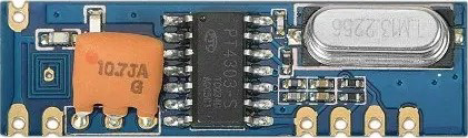
The 433MHz RF Receiver Module is an electronic component designed to receive radio frequency (RF) signals at the 433MHz frequency band. This frequency band is widely used for low-power, short-range communication in various devices such as remote controls, garage door openers, wireless sensor networks, and home automation systems. The module is popular due to its ease of use, low cost, and ability to interface with microcontrollers like the Arduino UNO.

Explore Projects Built with 433Mhz Ontvanger

Use Cirkit Designer to design, explore, and prototype these projects online. Some projects support real-time simulation. Click "Open Project" to start designing instantly!
433 MHz RF Transmitter and Receiver with Arduino UNO for Wireless Communication
Image of Wireless Communication: A project utilizing 433Mhz Ontvanger in a practical application
This circuit consists of two Arduino UNO microcontrollers, each connected to an RF 433 MHz Transmitter and a 433 MHz RF Receiver Module. The setup allows for wireless communication between the two Arduinos, enabling them to send and receive data over a 433 MHz RF link.
Cirkit Designer LogoOpen Project in Cirkit Designer
ESP32-Based RF Communication System with 433 MHz Modules
Image of 433 mhz: A project utilizing 433Mhz Ontvanger in a practical application
This circuit comprises an ESP32 microcontroller connected to a 433 MHz RF transmitter and receiver pair. The ESP32 is programmed to receive and decode RF signals through the receiver module, as well as send RF signals via the transmitter module. Additionally, the ESP32 can communicate with a Bluetooth device to exchange commands and data, and it uses an LED for status indication.
Cirkit Designer LogoOpen Project in Cirkit Designer
Arduino-Based Doppler Radar with RF Transmission and LCD Display
Image of Doppler Radar: A project utilizing 433Mhz Ontvanger in a practical application
This circuit features an Arduino UNO microcontroller interfaced with an RF 433 MHz Transmitter, a Transmitter RF Module, an LCD screen with I2C communication, and a doppler radar sensor. The Arduino controls the RF transmission and processes the doppler radar's signal, likely for motion detection purposes. The LCD screen is used to display information or statuses, and the RF modules enable wireless communication, possibly to transmit the processed radar data.
Cirkit Designer LogoOpen Project in Cirkit Designer
433 MHz RF Transmitter and Receiver with Arduino Uno for Wireless LED Control
Image of rf module up: A project utilizing 433Mhz Ontvanger in a practical application
This circuit consists of two Arduino Uno R3 microcontrollers communicating wirelessly using 433 MHz RF modules. One Arduino is connected to an RF transmitter to send data, while the other Arduino is connected to an RF receiver to receive data and control an LED based on the received signal.
Cirkit Designer LogoOpen Project in Cirkit Designer

Explore Projects Built with 433Mhz Ontvanger

Use Cirkit Designer to design, explore, and prototype these projects online. Some projects support real-time simulation. Click "Open Project" to start designing instantly!
Image of Wireless Communication: A project utilizing 433Mhz Ontvanger in a practical application
433 MHz RF Transmitter and Receiver with Arduino UNO for Wireless Communication
This circuit consists of two Arduino UNO microcontrollers, each connected to an RF 433 MHz Transmitter and a 433 MHz RF Receiver Module. The setup allows for wireless communication between the two Arduinos, enabling them to send and receive data over a 433 MHz RF link.
Cirkit Designer LogoOpen Project in Cirkit Designer
Image of 433 mhz: A project utilizing 433Mhz Ontvanger in a practical application
ESP32-Based RF Communication System with 433 MHz Modules
This circuit comprises an ESP32 microcontroller connected to a 433 MHz RF transmitter and receiver pair. The ESP32 is programmed to receive and decode RF signals through the receiver module, as well as send RF signals via the transmitter module. Additionally, the ESP32 can communicate with a Bluetooth device to exchange commands and data, and it uses an LED for status indication.
Cirkit Designer LogoOpen Project in Cirkit Designer
Image of Doppler Radar: A project utilizing 433Mhz Ontvanger in a practical application
Arduino-Based Doppler Radar with RF Transmission and LCD Display
This circuit features an Arduino UNO microcontroller interfaced with an RF 433 MHz Transmitter, a Transmitter RF Module, an LCD screen with I2C communication, and a doppler radar sensor. The Arduino controls the RF transmission and processes the doppler radar's signal, likely for motion detection purposes. The LCD screen is used to display information or statuses, and the RF modules enable wireless communication, possibly to transmit the processed radar data.
Cirkit Designer LogoOpen Project in Cirkit Designer
Image of rf module up: A project utilizing 433Mhz Ontvanger in a practical application
433 MHz RF Transmitter and Receiver with Arduino Uno for Wireless LED Control
This circuit consists of two Arduino Uno R3 microcontrollers communicating wirelessly using 433 MHz RF modules. One Arduino is connected to an RF transmitter to send data, while the other Arduino is connected to an RF receiver to receive data and control an LED based on the received signal.
Cirkit Designer LogoOpen Project in Cirkit Designer

Technical Specifications

Key Technical Details

  • Operating Frequency: 433MHz
  • Supply Voltage: 3.3V to 5V DC
  • Current Consumption: 5mA (typical at 5V)
  • Sensitivity: -105dBm (typical)
  • Modulation: OOK (On-Off Keying)
  • Operating Temperature: -10°C to +70°C

Pin Configuration and Descriptions

Pin Number Pin Name Description
1 VCC Power supply (3.3V to 5V DC)
2 DATA Data output (digital high/low signal)
3 GND Ground
4 ANT Antenna connection (for RF signal input)

Usage Instructions

Interfacing with a Circuit

  1. Power Supply: Connect the VCC pin to a 3.3V or 5V power supply from your microcontroller or breadboard power rail.
  2. Data Output: Connect the DATA pin to a digital input pin on your microcontroller.
  3. Ground: Connect the GND pin to the ground on your microcontroller or breadboard.
  4. Antenna: Attach a 17cm wire to the ANT pin to serve as an antenna for better signal reception.

Important Considerations and Best Practices

  • Antenna Length: For optimal performance, the length of the antenna should be approximately one-quarter of the wavelength of the frequency. For 433MHz, this is around 17cm.
  • Placement: Keep the receiver away from metal objects and noise sources such as motors and high-power electronics.
  • Power Supply: Ensure a stable power supply to avoid data errors.
  • Data Decoding: Use a library or write code to decode the signal received by the DATA pin.

Example Arduino Code

#include <RCSwitch.h>

RCSwitch mySwitch = RCSwitch();

void setup() {
  Serial.begin(9600);
  mySwitch.enableReceive(0);  // Receiver on interrupt 0 => that is pin #2
}

void loop() {
  if (mySwitch.available()) {
    int value = mySwitch.getReceivedValue();
    
    if (value == 0) {
      Serial.println("Unknown encoding");
    } else {
      Serial.print("Received ");
      Serial.println( mySwitch.getReceivedValue() );
    }
    mySwitch.resetAvailable();
  }
}

Troubleshooting and FAQs

Common Issues

  • No Data Received: Ensure the antenna is properly connected and the module is powered correctly.
  • Intermittent Data: Check for sources of interference and ensure the antenna is the correct length.
  • Garbled Data: Verify that the data decoding method matches the transmitter's encoding.

Solutions and Tips

  • Antenna Issues: If reception is poor, try repositioning the antenna or moving the receiver away from obstructions.
  • Power Issues: Use a regulated power supply to prevent voltage fluctuations that could affect the receiver.
  • Decoding: Use libraries like RCSwitch for Arduino to simplify the decoding process.

FAQs

Q: Can I use this module outdoors? A: Yes, but it should be enclosed in a weatherproof case to protect it from the elements.

Q: How far can the receiver pick up signals? A: The range depends on many factors, including antenna design, transmitter power, and environmental conditions. Typically, it can range from a few meters to over 100 meters in open space.

Q: Can the receiver work with any 433MHz transmitter? A: Generally, yes, as long as the transmitter uses a compatible modulation scheme (OOK) and the signal is within the receiver's sensitivity range.

Remember to always adhere to local regulations regarding the use of RF devices and ensure that your application does not interfere with other critical communications.