How to Use Adafruit Wii Nunchuck Breakout Adapter: Examples, Pinouts, and Specs
Introduction
The Adafruit Wii Nunchuck Breakout Adapter is a versatile and user-friendly interface board designed to connect the Wii Nunchuck controller to microcontroller projects. This adapter simplifies the process of tapping into the Nunchuck's accelerometer, joystick, and button inputs, making it an ideal choice for hobbyists and developers looking to incorporate intuitive control into their electronic creations. Common applications include robotics, gaming interfaces, and motion-sensitive projects.
Explore Projects Built with Adafruit Wii Nunchuck Breakout Adapter


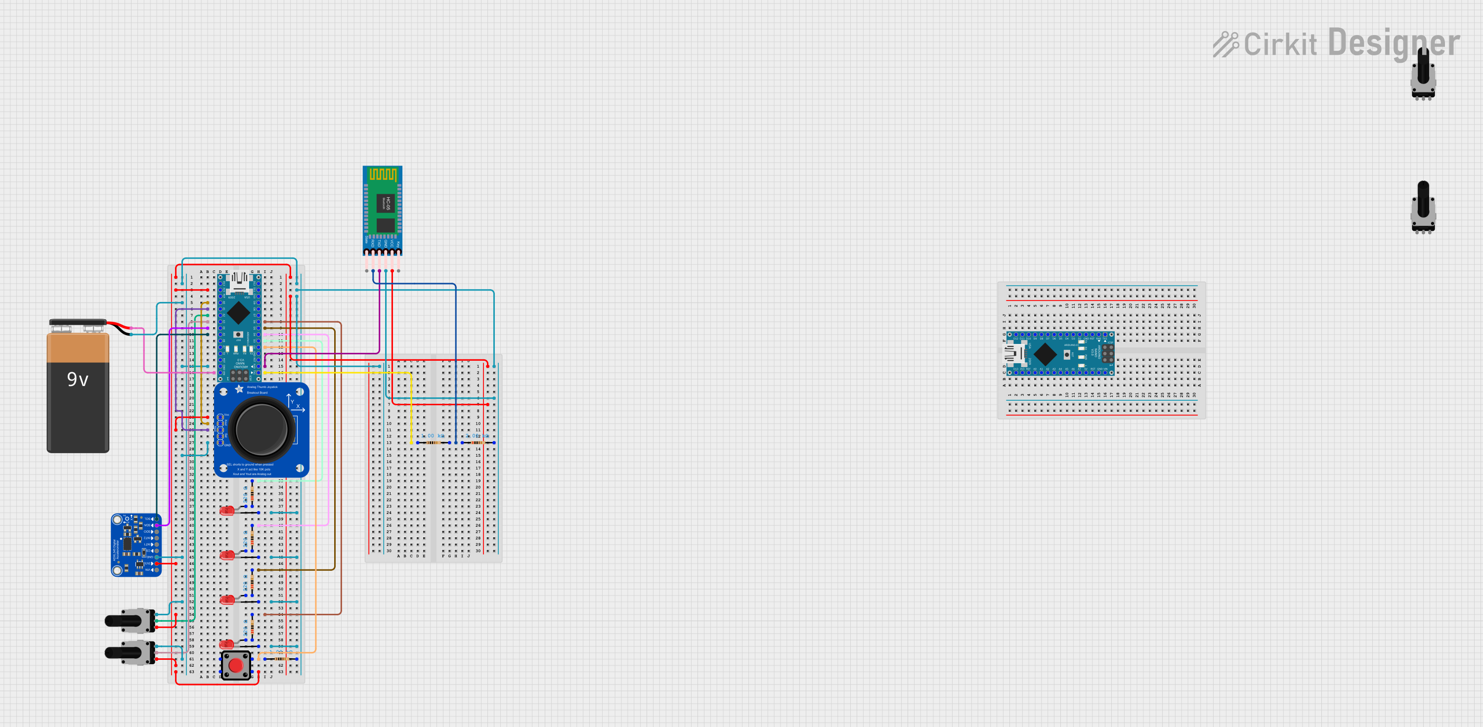
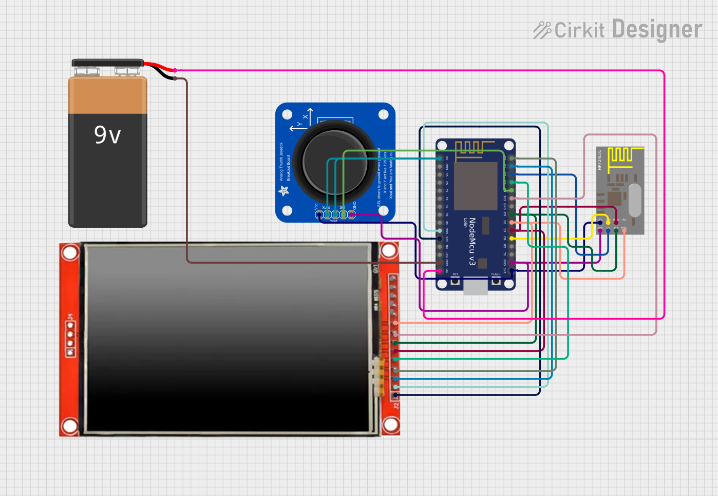
Explore Projects Built with Adafruit Wii Nunchuck Breakout Adapter
Technical Specifications
Key Technical Details
- Operating Voltage: 3.3V to 5V
- Communication Interface: I2C
- Dimensions: 0.8" x 0.6" x 0.1" (20mm x 15mm x 3mm)
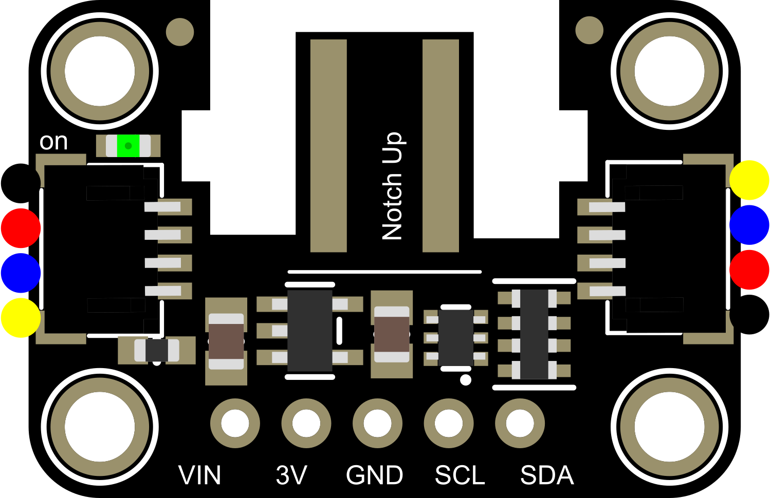
Pin Configuration and Descriptions
| Pin | Description |
|---|---|
| GND | Ground connection |
| 3V3 | 3.3V power supply input |
| 5V | 5V power supply input (with onboard regulator) |
| SDA | I2C Data line |
| SCL | I2C Clock line |
Usage Instructions
Connecting to a Circuit
- Power: Connect the 3V3 or 5V pin to the corresponding power supply on your microcontroller. If using 5V, the onboard regulator will step down the voltage to 3.3V required by the Nunchuck.
- Ground: Connect the GND pin to the ground on your microcontroller.
- I2C Communication: Connect the SDA and SCL pins to the I2C data and clock lines on your microcontroller.
Important Considerations and Best Practices
- Ensure that the power supply matches the requirements of your microcontroller to avoid damage.
- Use pull-up resistors on the SDA and SCL lines if your microcontroller does not have built-in pull-ups.
- When using with an Arduino UNO, connect SDA to A4 and SCL to A5.
Example Code for Arduino UNO
#include <Wire.h>

// Nunchuck I2C address (default)
const byte nunchuck_address = 0x52;

void setup() {
  Wire.begin(); // Initialize I2C
  Serial.begin(9600); // Start serial communication at 9600 baud

  // Initialize the Nunchuck
  Wire.beginTransmission(nunchuck_address);
  Wire.write(0xF0);
  Wire.write(0x55);
  Wire.endTransmission();
  delay(1);
  Wire.beginTransmission(nunchuck_address);
  Wire.write(0xFB);
  Wire.write(0x00);
  Wire.endTransmission();
}

void loop() {
  // Request data from Nunchuck
  Wire.requestFrom(nunchuck_address, 6);
  while (Wire.available()) {
    // Read the 6 bytes of data
    // joystick X, joystick Y, accelerometer X, Y, Z, buttons
    byte joystickX = Wire.read();
    byte joystickY = Wire.read();
    byte accelX = Wire.read();
    byte accelY = Wire.read();
    byte accelZ = Wire.read();
    byte buttons = Wire.read();

    // Process the data (e.g., print to serial)
    Serial.print("Joystick X: ");
    Serial.print(joystickX);
    Serial.print(" | Joystick Y: ");
    Serial.print(joystickY);
    // ... Add additional processing and output for accelerometer data and buttons

    // Prepare for next data packet
    Wire.beginTransmission(nunchuck_address);
    Wire.write(0x00);
    Wire.endTransmission();
    delay(100); // Delay before next read
  }
}
Troubleshooting and FAQs
Common Issues
- No Data Received: Ensure that the Nunchuck is properly connected and that the I2C address is correct.
- Inaccurate Readings: Verify that the Nunchuck is calibrated and that there are no loose connections.
- Intermittent Connection: Check for any physical damage to the Nunchuck cable or the adapter.
Solutions and Tips
- Double-check wiring, especially the SDA and SCL connections.
- Use the
Wirelibrary'ssetClock()function to adjust the I2C clock speed if necessary. - Ensure that the microcontroller's power supply is stable and within the acceptable range.
FAQs
Q: Can I use this adapter with a 5V microcontroller? A: Yes, the adapter has an onboard regulator for stepping down from 5V to 3.3V.
Q: Do I need to install any libraries to use this adapter with an Arduino?
A: The standard Wire library included with the Arduino IDE is sufficient for basic communication.
Q: How can I interpret the button data from the Nunchuck? A: The button data is typically provided as a byte where each bit represents a different button state. You'll need to use bitwise operations to extract the individual button states.
Remember to always handle electronic components with care and follow proper ESD safety procedures to prevent damage.