How to Use SSD1351: Examples, Pinouts, and Specs
Introduction
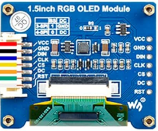
The SSD1351 is a low-power OLED display driver manufactured by Waveshare, with the part ID "1.5inch RGB OLED Module." It supports a resolution of 128x128 pixels and offers vibrant colors and high contrast, making it ideal for small display applications. The module communicates via SPI or I2C interfaces, making it compatible with a wide range of microcontrollers and embedded systems.
Explore Projects Built with SSD1351

Explore Projects Built with SSD1351
Common Applications and Use Cases
- Wearable devices
- Portable electronics
- Embedded system displays
- IoT dashboards
- Graphical user interfaces for small devices
Technical Specifications
The SSD1351 module is designed for high-performance, low-power operation. Below are its key technical details:
Key Specifications
| Parameter | Value |
|---|---|
| Manufacturer | Waveshare |
| Part ID | 1.5inch RGB OLED Module |
| Resolution | 128x128 pixels |
| Display Type | OLED (Organic Light Emitting Diode) |
| Interface | SPI / I2C |
| Operating Voltage | 3.3V / 5V |
| Power Consumption | Low power |
| Pixel Color Depth | 16-bit (65,536 colors) |
| Viewing Angle | >160° |
| Operating Temperature | -40°C to 70°C |
| Dimensions | 1.5 inches diagonal |
Pin Configuration and Descriptions
The SSD1351 module has a 7-pin interface for SPI communication. Below is the pinout:
| Pin Number | Pin Name | Description |
|---|---|---|
| 1 | GND | Ground pin |
| 2 | VCC | Power supply (3.3V or 5V) |
| 3 | SCL | Serial Clock Line (SPI clock input) |
| 4 | SDA | Serial Data Line (SPI data input) |
| 5 | RES | Reset pin (active low) |
| 6 | DC | Data/Command control pin |
| 7 | CS | Chip Select (active low) |
Usage Instructions
The SSD1351 module is straightforward to use in embedded systems. Below are the steps and considerations for integrating it into your project.
Connecting the SSD1351 to a Microcontroller
- Power Supply: Connect the
VCCpin to a 3.3V or 5V power source and theGNDpin to ground. - SPI Interface: Connect the
SCL,SDA,RES,DC, andCSpins to the corresponding SPI pins on your microcontroller. - Initialization: Use an appropriate library (e.g., Adafruit SSD1351 library) to initialize the display.
Example: Using SSD1351 with Arduino UNO
Below is an example of how to connect and program the SSD1351 module with an Arduino UNO using the SPI interface.
Wiring Diagram
| SSD1351 Pin | Arduino UNO Pin |
|---|---|
| GND | GND |
| VCC | 5V |
| SCL | D13 (SCK) |
| SDA | D11 (MOSI) |
| RES | D8 |
| DC | D9 |
| CS | D10 |
Arduino Code Example
#include <Adafruit_GFX.h>       // Include Adafruit GFX library for graphics
#include <Adafruit_SSD1351.h>   // Include Adafruit SSD1351 library for the display

// Define pin connections
#define OLED_CS   10  // Chip Select pin
#define OLED_DC   9   // Data/Command pin
#define OLED_RST  8   // Reset pin

// Create an instance of the SSD1351 display
Adafruit_SSD1351 display = Adafruit_SSD1351(128, 128, &SPI, OLED_CS, OLED_DC, OLED_RST);

void setup() {
  // Initialize the display
  display.begin();

  // Clear the display with a black background
  display.fillScreen(SSD1351_BLACK);

  // Display a message
  display.setTextColor(SSD1351_WHITE);
  display.setTextSize(1);
  display.setCursor(0, 0);
  display.println("Hello, SSD1351!");
}

void loop() {
  // Add your code here to update the display
}
Important Considerations and Best Practices
- Voltage Levels: Ensure the module is powered with the correct voltage (3.3V or 5V).
- SPI Speed: Use an appropriate SPI clock speed to avoid communication errors.
- Reset Pin: Always connect the
RESpin to ensure proper initialization. - Library Support: Use a compatible library like Adafruit SSD1351 for easier integration.
Troubleshooting and FAQs
Common Issues and Solutions
Display Not Turning On
- Cause: Incorrect wiring or power supply.
- Solution: Double-check all connections and ensure the module is powered correctly.
Flickering or Artifacts on the Display
- Cause: SPI clock speed too high.
- Solution: Reduce the SPI clock speed in your microcontroller settings.
No Response from the Display
- Cause: Incorrect initialization or library issues.
- Solution: Verify that the correct library is installed and initialized properly.
Partial or Distorted Graphics
- Cause: Data/Command pin misconfigured.
- Solution: Ensure the
DCpin is connected to the correct microcontroller pin.
FAQs
Q: Can I use the SSD1351 with a 5V microcontroller?
A: Yes, the module supports both 3.3V and 5V logic levels, making it compatible with 5V microcontrollers like Arduino UNO.
Q: Does the SSD1351 support I2C communication?
A: While the SSD1351 driver supports I2C, the Waveshare 1.5inch RGB OLED Module is typically configured for SPI communication.
Q: How do I display images on the SSD1351?
A: Use a graphics library like Adafruit GFX to load and render bitmap images onto the display.
Q: What is the maximum refresh rate of the SSD1351?
A: The refresh rate depends on the SPI clock speed and the microcontroller's processing power. Typically, it is sufficient for smooth animations.
By following this documentation, you can successfully integrate and use the SSD1351 module in your projects!