Cirkit Designer Logo
Cirkit Designer
Your all-in-one circuit design IDE
Home / 
Component Documentation

How to Use ELRS Lite RX: Examples, Pinouts, and Specs

Image of ELRS Lite RX
Cirkit Designer LogoDesign with ELRS Lite RX in Cirkit Designer

Introduction

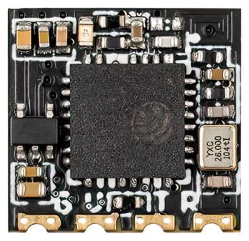
The ELRS Lite RX by BetaFPV is a compact and lightweight receiver module designed for long-range (LR) remote-controlled (RC) applications. It utilizes the open-source ExpressLRS (ELRS) protocol, which is known for its high performance and low latency communication. This receiver is ideal for use in radio-controlled aircraft, drones, and other vehicles where reliable long-range communication is essential.

Explore Projects Built with ELRS Lite RX

Use Cirkit Designer to design, explore, and prototype these projects online. Some projects support real-time simulation. Click "Open Project" to start designing instantly!
Dual-Mode LoRa and GSM Communication Device with ESP32
Image of modul gateway: A project utilizing ELRS Lite RX in a practical application
This circuit features an ESP32 Devkit V1 microcontroller interfaced with an RFM95 LoRa transceiver module for long-range communication and a SIM800L GSM module for cellular connectivity. Two LM2596 step-down modules are used to regulate the 12V battery voltage down to 3.3V required by the ESP32, RFM95, and SIM800L. The ESP32 facilitates data exchange between the RFM95 and SIM800L, enabling the system to send/receive data over both LoRa and GSM networks.
Cirkit Designer LogoOpen Project in Cirkit Designer
ESP32-Based RF Communication System with 433 MHz Modules
Image of 433 mhz: A project utilizing ELRS Lite RX in a practical application
This circuit comprises an ESP32 microcontroller connected to a 433 MHz RF transmitter and receiver pair. The ESP32 is programmed to receive and decode RF signals through the receiver module, as well as send RF signals via the transmitter module. Additionally, the ESP32 can communicate with a Bluetooth device to exchange commands and data, and it uses an LED for status indication.
Cirkit Designer LogoOpen Project in Cirkit Designer
ESP8266 NodeMCU Wi-Fi Enabled OLED Display with RYLR896 Communication Module
Image of Smart Irrigation system Rx Side: A project utilizing ELRS Lite RX in a practical application
This circuit features an ESP8266 NodeMCU microcontroller connected to a 0.96" OLED display and an RYLR896 LoRa module. The ESP8266 communicates with the OLED via I2C protocol and interfaces with the LoRa module using UART, enabling wireless data transmission and display capabilities.
Cirkit Designer LogoOpen Project in Cirkit Designer
Arduino UNO and LoRa E220 Wireless Communication Module with Resistor Network
Image of Conexion LoRa: A project utilizing ELRS Lite RX in a practical application
This circuit features an Arduino UNO microcontroller interfaced with an EBYTE LoRa E220 module for wireless communication. The circuit includes two resistors for signal conditioning, with one resistor connected to the Arduino's D9 pin and the other forming part of the connection between the LoRa module's RXD pin and ground. The Arduino controls the LoRa module's mode and communication through its digital pins.
Cirkit Designer LogoOpen Project in Cirkit Designer

Explore Projects Built with ELRS Lite RX

Use Cirkit Designer to design, explore, and prototype these projects online. Some projects support real-time simulation. Click "Open Project" to start designing instantly!
Image of modul gateway: A project utilizing ELRS Lite RX in a practical application
Dual-Mode LoRa and GSM Communication Device with ESP32
This circuit features an ESP32 Devkit V1 microcontroller interfaced with an RFM95 LoRa transceiver module for long-range communication and a SIM800L GSM module for cellular connectivity. Two LM2596 step-down modules are used to regulate the 12V battery voltage down to 3.3V required by the ESP32, RFM95, and SIM800L. The ESP32 facilitates data exchange between the RFM95 and SIM800L, enabling the system to send/receive data over both LoRa and GSM networks.
Cirkit Designer LogoOpen Project in Cirkit Designer
Image of 433 mhz: A project utilizing ELRS Lite RX in a practical application
ESP32-Based RF Communication System with 433 MHz Modules
This circuit comprises an ESP32 microcontroller connected to a 433 MHz RF transmitter and receiver pair. The ESP32 is programmed to receive and decode RF signals through the receiver module, as well as send RF signals via the transmitter module. Additionally, the ESP32 can communicate with a Bluetooth device to exchange commands and data, and it uses an LED for status indication.
Cirkit Designer LogoOpen Project in Cirkit Designer
Image of Smart Irrigation system Rx Side: A project utilizing ELRS Lite RX in a practical application
ESP8266 NodeMCU Wi-Fi Enabled OLED Display with RYLR896 Communication Module
This circuit features an ESP8266 NodeMCU microcontroller connected to a 0.96" OLED display and an RYLR896 LoRa module. The ESP8266 communicates with the OLED via I2C protocol and interfaces with the LoRa module using UART, enabling wireless data transmission and display capabilities.
Cirkit Designer LogoOpen Project in Cirkit Designer
Image of Conexion LoRa: A project utilizing ELRS Lite RX in a practical application
Arduino UNO and LoRa E220 Wireless Communication Module with Resistor Network
This circuit features an Arduino UNO microcontroller interfaced with an EBYTE LoRa E220 module for wireless communication. The circuit includes two resistors for signal conditioning, with one resistor connected to the Arduino's D9 pin and the other forming part of the connection between the LoRa module's RXD pin and ground. The Arduino controls the LoRa module's mode and communication through its digital pins.
Cirkit Designer LogoOpen Project in Cirkit Designer

Common Applications and Use Cases

  • Remote control aircraft and drones
  • Long-range RC boats
  • Robotics and unmanned vehicles
  • FPV (First Person View) racing and casual flying

Technical Specifications

Key Technical Details

  • Frequency Bands: 2.4GHz ISM
  • Protocol: ExpressLRS
  • Output Power: Up to 100mW
  • Input Voltage: 5V
  • Telemetry: Yes, with power and signal strength indication
  • Antenna Connector: IPEX / u.FL
  • Firmware: Updatable via BetaFPV configurator

Pin Configuration and Descriptions

Pin Number Description Voltage/Signal
1 GND (Ground) -
2 5V (Power Supply) 5V
3 TX (UART Transmit) 3.3V Logic
4 RX (UART Receive) 3.3V Logic
5 S.Port (Telemetry) 3.3V Logic

Usage Instructions

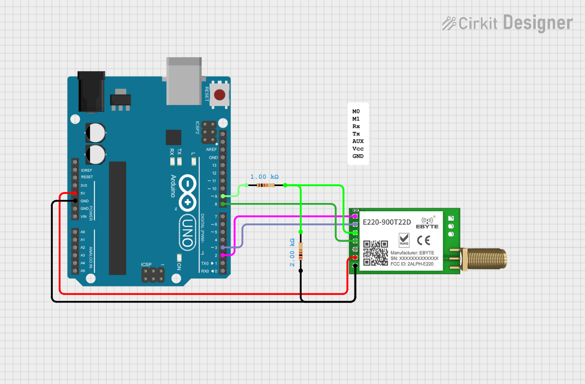
How to Use the Component in a Circuit

  1. Power Supply: Connect the 5V and GND pins to a stable 5V power source.
  2. UART Connection: Connect the TX and RX pins to the corresponding UART RX and TX pins on your flight controller.
  3. Telemetry: If telemetry is desired, connect the S.Port pin to a telemetry-capable UART on your flight controller.
  4. Antenna: Attach the antenna to the IPEX/u.FL connector, ensuring it is secure and positioned for optimal signal reception.
  5. Binding: Follow the manufacturer's instructions to bind the ELRS Lite RX with your ELRS-compatible transmitter.

Important Considerations and Best Practices

  • Ensure the antenna is properly installed and not obstructed for maximum range.
  • Avoid placing the receiver next to high-power components to minimize interference.
  • Update the firmware regularly to benefit from improvements and bug fixes.
  • Use a capacitor to filter power supply noise if necessary.

Troubleshooting and FAQs

Common Issues

  • Binding Issues: Ensure both the transmitter and receiver are on the same firmware version.
  • Range Problems: Check the antenna placement and ensure there are no obstructions or sources of interference.
  • Telemetry Not Working: Verify the telemetry connection and ensure the flight controller is configured correctly.

Solutions and Tips for Troubleshooting

  • Firmware Mismatch: Update both the transmitter module and receiver to the latest compatible firmware.
  • Poor Range: Reposition the antenna, check for damage, or consider using a higher gain antenna.
  • Telemetry Configuration: Double-check the port configuration in your flight controller's software to ensure telemetry is enabled.

Example Code for Arduino UNO

#include <SoftwareSerial.h>

SoftwareSerial mySerial(10, 11); // RX, TX

void setup() {
  // Start the hardware serial communication
  Serial.begin(9600);
  
  // Start the software serial communication
  mySerial.begin(9600);
  
  // Print a message to the serial monitor
  Serial.println("ELRS Lite RX Example");
}

void loop() {
  // Check if data has been received from the receiver
  if (mySerial.available()) {
    // Read the data and print it to the serial monitor
    Serial.print("Received: ");
    Serial.println(mySerial.read());
  }
  
  // Check if data has been received from the serial monitor
  if (Serial.available()) {
    // Send the data to the receiver
    mySerial.write(Serial.read());
  }
}

Note: This example uses SoftwareSerial to create a serial connection on pins 10 and 11 of the Arduino UNO. The ELRS Lite RX should be connected to these pins for the example to work. Adjust the baud rate as necessary to match the ELRS Lite RX configuration.

Remember to consult the BetaFPV documentation for specific instructions on binding and configuring the ELRS Lite RX with your transmitter and flight controller.