How to Use Battery Switch ON/OFF 275A: Examples, Pinouts, and Specs
Introduction
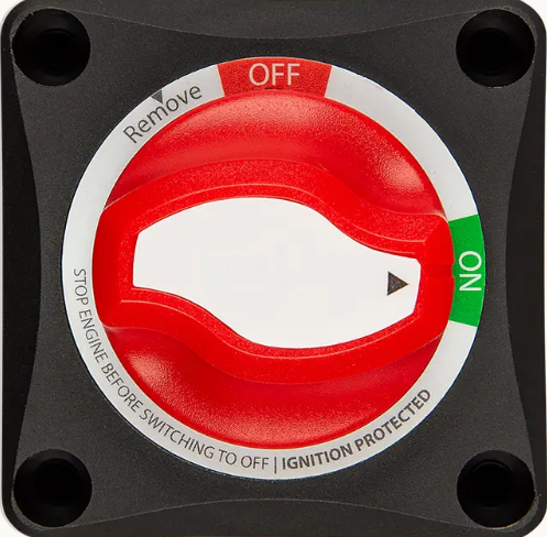
The Battery Switch ON/OFF 275A is a heavy-duty switch designed to connect or disconnect a battery from an electrical circuit. With a current handling capacity of up to 275 amps, this switch ensures safe operation and maintenance of electrical systems. It is commonly used in automotive, marine, and industrial applications where high-current battery isolation is required. The switch provides a reliable way to prevent battery drain, isolate power during maintenance, and enhance safety in electrical systems.
Explore Projects Built with Battery Switch ON/OFF 275A


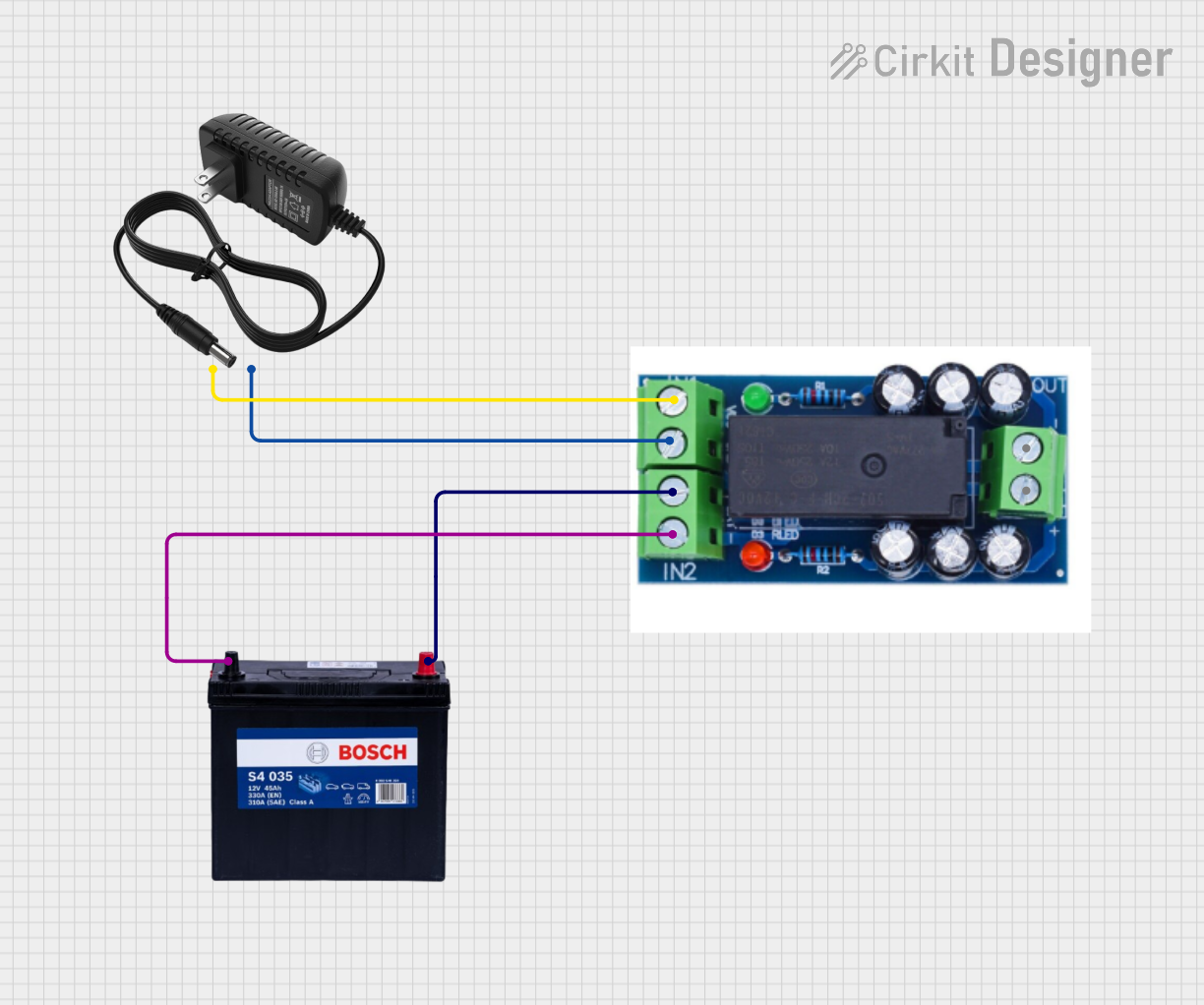
Explore Projects Built with Battery Switch ON/OFF 275A
Common Applications and Use Cases
- Automotive systems for battery isolation in vehicles.
- Marine applications to disconnect batteries during maintenance or storage.
- Industrial machinery requiring high-current battery management.
- Backup power systems to safely isolate batteries when not in use.
- Recreational vehicles (RVs) and off-grid solar systems for power control.
Technical Specifications
The following table outlines the key technical details of the Battery Switch ON/OFF 275A:
| Parameter | Value |
|---|---|
| Maximum Current Rating | 275A |
| Voltage Rating | 12V - 48V DC |
| Operating Temperature | -40°C to 85°C |
| Housing Material | High-strength ABS plastic |
| Mounting Type | Surface or panel mount |
| Switch Positions | ON (Closed), OFF (Open) |
| Terminal Type | M10 threaded studs |
| Dimensions | 69mm x 69mm x 75mm |
| Weight | Approximately 200g |
Pin Configuration and Descriptions
The Battery Switch ON/OFF 275A has two main terminals for connection:
| Terminal | Description |
|---|---|
| Terminal 1 | Connects to the positive terminal of the battery. |
| Terminal 2 | Connects to the positive terminal of the load (e.g., vehicle, inverter, etc.). |
Usage Instructions
How to Use the Component in a Circuit
- Mounting the Switch: Securely mount the switch on a flat surface or panel using the provided mounting holes. Ensure the switch is easily accessible for operation.
- Connecting the Battery:
- Connect Terminal 1 to the positive terminal of the battery using a suitable high-current cable.
- Connect Terminal 2 to the positive terminal of the load (e.g., vehicle electrical system, inverter, etc.).
- Operation:
- Turn the switch to the "ON" position to connect the battery to the circuit.
- Turn the switch to the "OFF" position to disconnect the battery from the circuit.
Important Considerations and Best Practices
- Cable Selection: Use cables rated for at least 275A to ensure safe operation and minimize voltage drop.
- Secure Connections: Tighten all terminal connections properly to avoid loose contacts, which can lead to overheating or arcing.
- Environmental Protection: If used in marine or outdoor environments, ensure the switch is protected from water and corrosion.
- Load Isolation: Always turn the switch to the "OFF" position before performing maintenance on the electrical system.
- Avoid Overloading: Do not exceed the maximum current rating of 275A to prevent damage to the switch.
Arduino UNO Integration
While the Battery Switch ON/OFF 275A is not directly controlled by an Arduino, it can be used in conjunction with an Arduino-based system for monitoring or automation. For example, you can use a current sensor to monitor the battery's current flow and control a relay to automate the switch operation. Below is an example Arduino code snippet for monitoring current:
/*
  Example: Monitoring battery current using an ACS712 current sensor
  and displaying the value on the Serial Monitor.
*/

const int currentSensorPin = A0; // Connect the ACS712 output to Arduino A0
const float sensitivity = 0.185; // Sensitivity for ACS712 (e.g., 185mV/A for 5A model)
const float offsetVoltage = 2.5; // Offset voltage at 0A (for 5V supply)

void setup() {
  Serial.begin(9600); // Initialize Serial Monitor
  pinMode(currentSensorPin, INPUT); // Set the sensor pin as input
}

void loop() {
  int sensorValue = analogRead(currentSensorPin); // Read the sensor value
  float voltage = (sensorValue / 1023.0) * 5.0; // Convert to voltage
  float current = (voltage - offsetVoltage) / sensitivity; // Calculate current

  // Print the current value to the Serial Monitor
  Serial.print("Current: ");
  Serial.print(current, 2); // Print with 2 decimal places
  Serial.println(" A");

  delay(1000); // Wait for 1 second before the next reading
}
Troubleshooting and FAQs
Common Issues and Solutions
| Issue | Possible Cause | Solution |
|---|---|---|
| Switch does not turn ON or OFF | Loose or corroded terminal connections | Check and tighten all connections. Clean terminals if corrosion is present. |
| Overheating of the switch | Exceeding the current rating of 275A | Ensure the load current does not exceed 275A. Use a higher-rated switch if needed. |
| Arcing or sparking during operation | Loose connections or switching under load | Tighten connections and avoid switching under heavy load conditions. |
| Switch fails to isolate the battery | Internal damage to the switch | Replace the switch if internal damage is suspected. |
FAQs
Can this switch be used for both 12V and 24V systems?
- Yes, the switch supports a voltage range of 12V to 48V DC, making it suitable for 12V, 24V, and 48V systems.
Is the switch waterproof?
- The switch is not fully waterproof. For marine or outdoor use, ensure it is installed in a protected enclosure.
Can I use this switch for AC circuits?
- No, this switch is designed for DC circuits only. Using it in AC circuits may result in damage or unsafe operation.
What type of cables should I use with this switch?
- Use high-current cables rated for at least 275A. Ensure the cable insulation is suitable for the operating environment.
Can I mount the switch in any orientation?
- Yes, the switch can be mounted in any orientation, but ensure it is easily accessible for operation.