How to Use buzzer: Examples, Pinouts, and Specs
Introduction
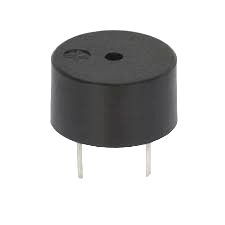
A buzzer is an audio signaling device that can be found in a wide range of electronic applications. It is commonly used to produce sound or alarm in electronic circuits. Buzzers can be categorized into two main types: active and passive. An active buzzer generates a sound at a specific frequency when supplied with power, while a passive buzzer requires an external frequency (AC signal) to produce sound.
Explore Projects Built with buzzer
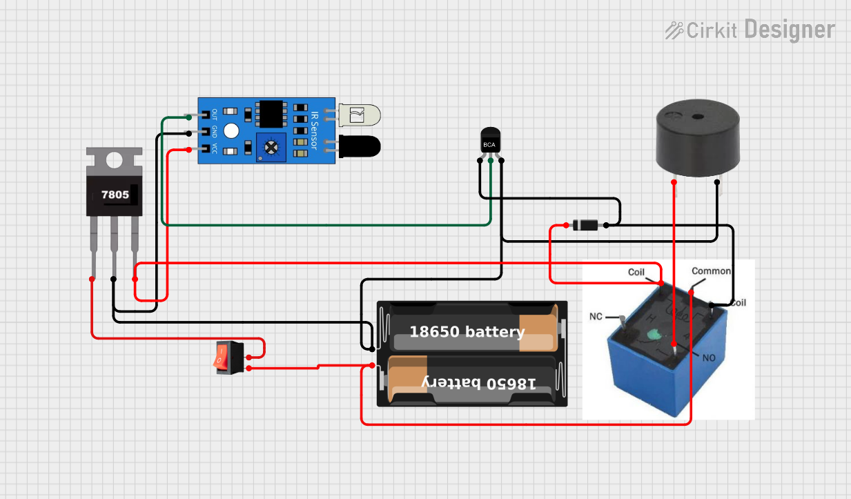
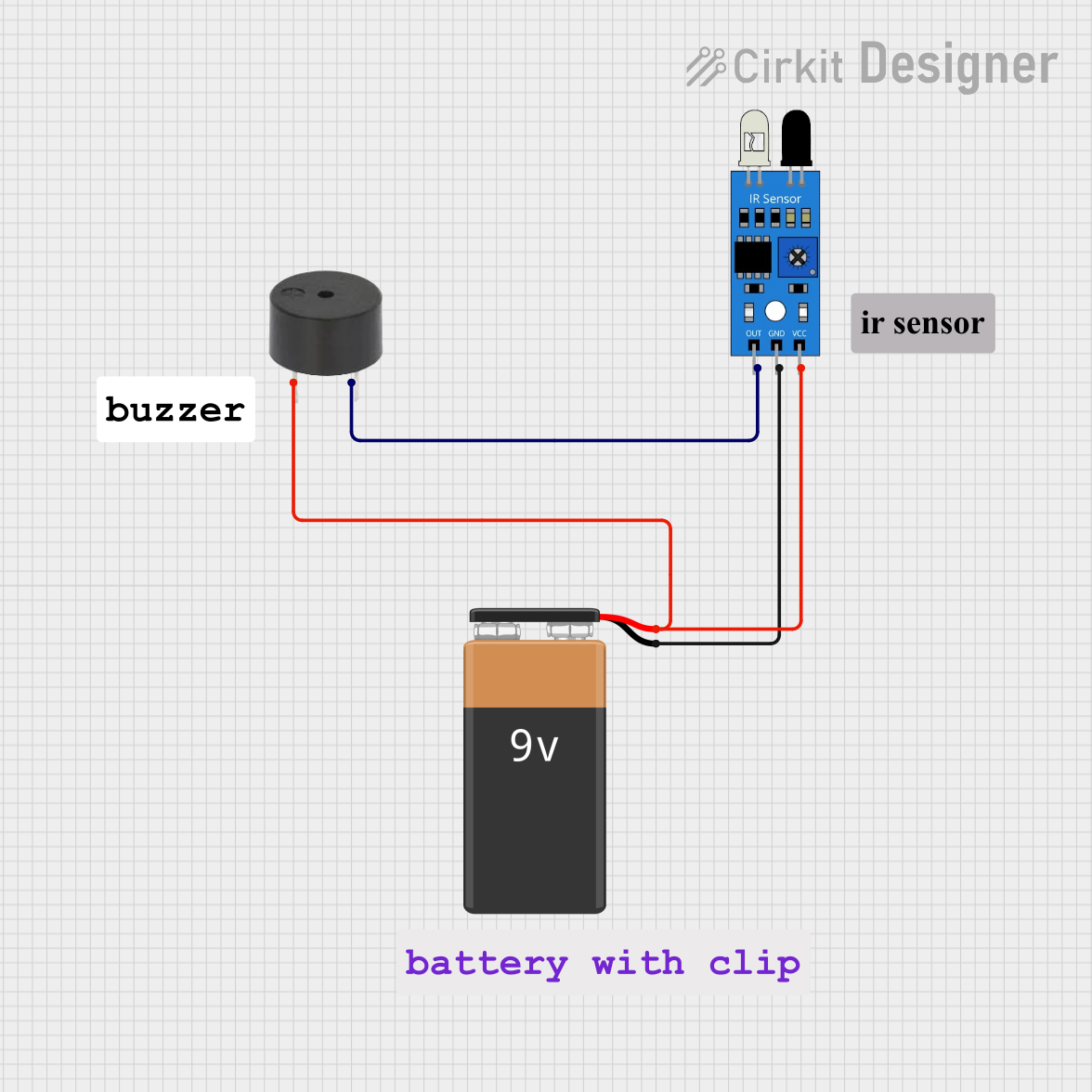

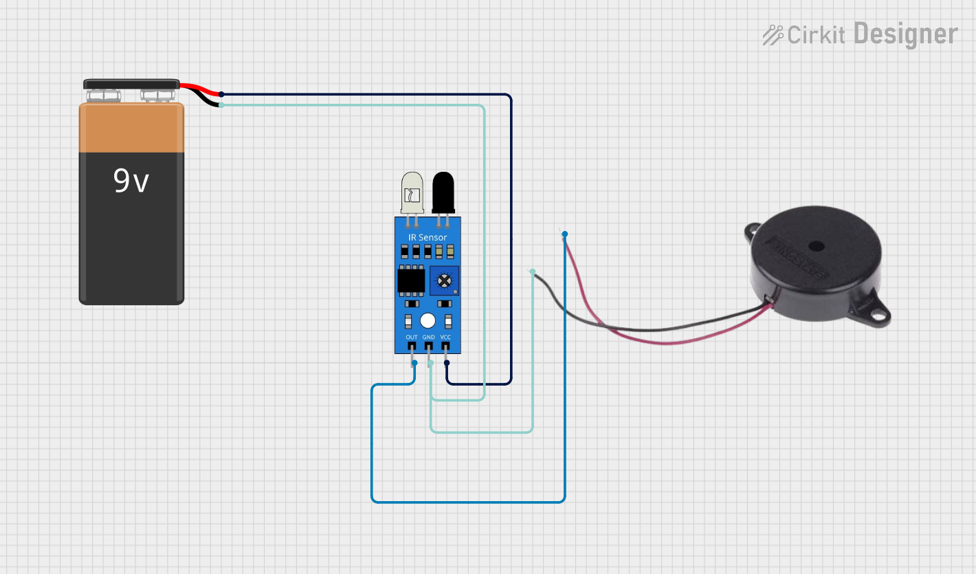
Explore Projects Built with buzzer
Common Applications and Use Cases
- Alarm systems
- Timers
- Electronic toys
- User input feedback for devices (e.g., pressing a button)
- Warning signals for industrial machines
Technical Specifications
Key Technical Details
- Operating Voltage: Typically 3V to 12V for passive buzzers, 5V for active buzzers
- Current Consumption: Varies with the buzzer model, usually in the range of 5mA to 30mA
- Sound Output: Measured in decibels (dB), varies depending on the buzzer size and voltage
- Frequency Range: Typically around 2kHz for active buzzers, depends on the input signal for passive buzzers
Pin Configuration and Descriptions
| Pin Number | Description | Notes |
|---|---|---|
| 1 | Positive (VCC) | Connect to positive power supply |
| 2 | Negative (GND) | Connect to ground |
Usage Instructions
How to Use the Buzzer in a Circuit
- Identify the type of buzzer (active or passive).
- Connect the positive pin of the buzzer to the output pin of the microcontroller or power source.
- Connect the negative pin to the ground (GND).
- For passive buzzers, generate a PWM signal from the microcontroller to the positive pin to create sound.
Important Considerations and Best Practices
- Do not exceed the maximum rated voltage of the buzzer.
- Use a current-limiting resistor if necessary to prevent damage to the buzzer.
- For passive buzzers, ensure the frequency of the input signal is within the audible range (typically 20Hz to 20kHz).
Example Code for Arduino UNO
// Define the buzzer pin
int buzzerPin = 9;

void setup() {
  // Set the buzzer pin as an output
  pinMode(buzzerPin, OUTPUT);
}

void loop() {
  // Turn on the buzzer at 1kHz frequency for 1 second
  tone(buzzerPin, 1000, 1000);
  delay(1500); // Wait for 1.5 seconds

  // Turn off the buzzer
  noTone(buzzerPin);
  delay(1000); // Wait for 1 second
}
Troubleshooting and FAQs
Common Issues Users Might Face
- Buzzer not sounding: Ensure the buzzer is correctly connected with the polarity in mind. For passive buzzers, check the frequency of the input signal.
- Low sound output: Verify that the voltage applied to the buzzer is within its operating range. Increase the voltage if it's too low, without exceeding the maximum rating.
- Distorted sound: This could be due to an incorrect frequency for passive buzzers or a damaged buzzer.
Solutions and Tips for Troubleshooting
- Double-check the wiring and connections.
- Use a multimeter to verify the voltage at the buzzer's terminals.
- Replace the buzzer if it appears to be damaged or if the sound quality does not improve with troubleshooting.
FAQs
Q: Can I use a passive buzzer without a microcontroller? A: Yes, but you will need an external AC signal source to drive the buzzer.
Q: How do I adjust the volume of the buzzer? A: The volume is typically adjusted by changing the voltage applied to the buzzer. However, this should be done within the buzzer's specified operating range.
Q: Can I use the same code for an active buzzer?
A: Yes, the tone() function can be used with an active buzzer, but the sound frequency is predetermined by the buzzer's internal circuitry, so the frequency parameter will not have an effect.