Cirkit Designer Logo
Cirkit Designer
Your all-in-one circuit design IDE
Home / 
Component Documentation

How to Use AMIS-30543 Stepper Motor Driver Carrier: Examples, Pinouts, and Specs

Image of AMIS-30543 Stepper Motor Driver Carrier
Cirkit Designer LogoDesign with AMIS-30543 Stepper Motor Driver Carrier in Cirkit Designer

Introduction

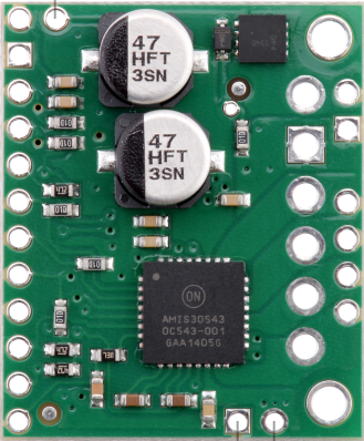
The AMIS-30543 Stepper Motor Driver Carrier (Pololu part #2970) is a compact and versatile stepper motor driver designed for precise control of stepper motors. It features adjustable current control, microstepping capabilities, and built-in protection mechanisms, making it ideal for a wide range of applications. This driver is based on the ON Semiconductor AMIS-30543 IC and is capable of driving bipolar stepper motors with high efficiency and reliability.

Explore Projects Built with AMIS-30543 Stepper Motor Driver Carrier

Use Cirkit Designer to design, explore, and prototype these projects online. Some projects support real-time simulation. Click "Open Project" to start designing instantly!
RFID-Activated Traffic Light Controller with Auditory Feedback Using Arduino Mega
Image of test: A project utilizing AMIS-30543 Stepper Motor Driver Carrier in a practical application
This circuit is designed to control two 28BYJ-48 stepper motors using A4988 stepper motor driver carriers, with an Arduino Mega 2560 as the central microcontroller. It includes an RFID-RC522 module for RFID reading, an LCD display for user interface, and a traffic light and piezo speaker for visual and audio signaling. The circuit is powered by a 12V 5A power supply, which is stepped down to 5V for logic level components, and it interfaces with a power outlet for AC to DC conversion.
Cirkit Designer LogoOpen Project in Cirkit Designer
CNC Machine Control System with Dual tb6600 Stepper Drivers and MAch3 USB Interface
Image of Jayshree CNC: A project utilizing AMIS-30543 Stepper Motor Driver Carrier in a practical application
This circuit appears to be a control system for a CNC machine or similar automated equipment. It includes two tb6600 Micro Stepping Motor Drivers for controlling stepper motors, a DC power source with a step-down buck converter to provide the necessary voltage levels, and a 4-channel relay module for switching higher power loads. The MAch3 CNC USB interface suggests the system is designed to interface with computer numerical control software, and the RMCS_3001 BLDC Driver indicates the presence of a brushless DC motor control. The Tiva C launchpad microcontroller and various connectors imply that the system is modular and may be programmable for specific automation tasks.
Cirkit Designer LogoOpen Project in Cirkit Designer
Stepper Motor Control System with TB6600 Driver and DKC-1A Controller
Image of Copy of Copy of PLC-Based Step Motor Speed and Direction Control System: A project utilizing AMIS-30543 Stepper Motor Driver Carrier in a practical application
This circuit controls a bipolar stepper motor using a tb6600 micro stepping motor driver and a DKC-1A stepper motor controller. The system is powered by a 24VDC power supply and includes a relay module for additional control functionalities.
Cirkit Designer LogoOpen Project in Cirkit Designer
Arduino Mega 2560-Controlled Stepper Motors with RFID Access and Traffic Light Indication
Image of Copy of test: A project utilizing AMIS-30543 Stepper Motor Driver Carrier in a practical application
This circuit controls two 28BYJ-48 stepper motors using A4988 stepper motor driver carriers, interfaced with an Arduino Mega 2560 microcontroller. It features an RFID-RC522 module for RFID reading, a 16x4 LCD display with I2C interface for user interaction, and a piezo speaker for audio feedback. Additionally, there is a traffic light module controlled by the Arduino, and a 48V to 5V converter to step down voltage for the logic levels. The power supply provides 12V to the motor drivers and is connected to a standard power outlet.
Cirkit Designer LogoOpen Project in Cirkit Designer

Explore Projects Built with AMIS-30543 Stepper Motor Driver Carrier

Use Cirkit Designer to design, explore, and prototype these projects online. Some projects support real-time simulation. Click "Open Project" to start designing instantly!
Image of test: A project utilizing AMIS-30543 Stepper Motor Driver Carrier in a practical application
RFID-Activated Traffic Light Controller with Auditory Feedback Using Arduino Mega
This circuit is designed to control two 28BYJ-48 stepper motors using A4988 stepper motor driver carriers, with an Arduino Mega 2560 as the central microcontroller. It includes an RFID-RC522 module for RFID reading, an LCD display for user interface, and a traffic light and piezo speaker for visual and audio signaling. The circuit is powered by a 12V 5A power supply, which is stepped down to 5V for logic level components, and it interfaces with a power outlet for AC to DC conversion.
Cirkit Designer LogoOpen Project in Cirkit Designer
Image of Jayshree CNC: A project utilizing AMIS-30543 Stepper Motor Driver Carrier in a practical application
CNC Machine Control System with Dual tb6600 Stepper Drivers and MAch3 USB Interface
This circuit appears to be a control system for a CNC machine or similar automated equipment. It includes two tb6600 Micro Stepping Motor Drivers for controlling stepper motors, a DC power source with a step-down buck converter to provide the necessary voltage levels, and a 4-channel relay module for switching higher power loads. The MAch3 CNC USB interface suggests the system is designed to interface with computer numerical control software, and the RMCS_3001 BLDC Driver indicates the presence of a brushless DC motor control. The Tiva C launchpad microcontroller and various connectors imply that the system is modular and may be programmable for specific automation tasks.
Cirkit Designer LogoOpen Project in Cirkit Designer
Image of Copy of Copy of PLC-Based Step Motor Speed and Direction Control System: A project utilizing AMIS-30543 Stepper Motor Driver Carrier in a practical application
Stepper Motor Control System with TB6600 Driver and DKC-1A Controller
This circuit controls a bipolar stepper motor using a tb6600 micro stepping motor driver and a DKC-1A stepper motor controller. The system is powered by a 24VDC power supply and includes a relay module for additional control functionalities.
Cirkit Designer LogoOpen Project in Cirkit Designer
Image of Copy of test: A project utilizing AMIS-30543 Stepper Motor Driver Carrier in a practical application
Arduino Mega 2560-Controlled Stepper Motors with RFID Access and Traffic Light Indication
This circuit controls two 28BYJ-48 stepper motors using A4988 stepper motor driver carriers, interfaced with an Arduino Mega 2560 microcontroller. It features an RFID-RC522 module for RFID reading, a 16x4 LCD display with I2C interface for user interaction, and a piezo speaker for audio feedback. Additionally, there is a traffic light module controlled by the Arduino, and a 48V to 5V converter to step down voltage for the logic levels. The power supply provides 12V to the motor drivers and is connected to a standard power outlet.
Cirkit Designer LogoOpen Project in Cirkit Designer

Common Applications

  • 3D printers
  • CNC machines
  • Robotics
  • Automated machinery
  • Precision positioning systems

Technical Specifications

The following table outlines the key technical details of the AMIS-30543 Stepper Motor Driver Carrier:

Parameter Value
Operating Voltage 8 V to 29 V
Maximum Output Current 1.6 A per phase (continuous)
Microstepping Modes Full-step, half-step, 1/4-step, 1/8-step, 1/16-step
Logic Voltage 3.3 V or 5 V (logic level compatible)
Communication Interface SPI (Serial Peripheral Interface)
Protection Features Overcurrent, overtemperature, undervoltage lockout, and short-circuit
Dimensions 0.6" × 0.8" (15 mm × 20 mm)

Pin Configuration and Descriptions

The AMIS-30543 Stepper Motor Driver Carrier has 16 pins. The table below describes each pin:

Pin Name Description
1 VBB Motor power supply (8 V to 29 V). Connect to the positive terminal of the motor power source.
2 GND Ground connection. Connect to the ground of the motor power source.
3 SDI SPI data input. Used for communication with the microcontroller.
4 SDO SPI data output. Used for communication with the microcontroller.
5 SCK SPI clock input.
6 CS SPI chip select. Active low.
7 EN Enable input. Active high. Enables the driver when high.
8 DIR Direction input. Determines the rotation direction of the stepper motor.
9 STEP Step input. A rising edge triggers a step.
10 RESET Reset input. Active low. Resets the driver when pulled low.
11 VDD Logic voltage supply (3.3 V or 5 V).
12 REF Reference voltage for current control.
13-16 OUT1A, OUT1B, OUT2A, OUT2B Motor outputs. Connect to the stepper motor windings.

Usage Instructions

How to Use the AMIS-30543 in a Circuit

  1. Power Supply: Connect the motor power supply (8 V to 29 V) to the VBB pin and ground to the GND pin. Ensure the power supply can provide sufficient current for your stepper motor.
  2. Logic Voltage: Connect the VDD pin to the logic voltage of your microcontroller (3.3 V or 5 V).
  3. Motor Connections: Connect the stepper motor windings to the OUT1A, OUT1B, OUT2A, and OUT2B pins.
  4. SPI Communication: Connect the SDI, SDO, SCK, and CS pins to the corresponding SPI pins on your microcontroller.
  5. Control Pins:
    • Use the STEP pin to send step pulses to the driver.
    • Use the DIR pin to control the rotation direction.
    • Use the EN pin to enable or disable the driver.
    • Optionally, use the RESET pin to reset the driver.

Important Considerations and Best Practices

  • Current Limiting: Adjust the reference voltage on the REF pin to set the current limit for your stepper motor. This prevents overheating and damage to the motor.
  • Microstepping: Configure the microstepping mode via SPI commands for smoother motor operation and higher resolution.
  • Heat Dissipation: Ensure adequate cooling for the driver, especially when operating at high currents.
  • Protection Features: The driver includes built-in protection features, but ensure proper wiring and avoid short circuits to prevent damage.

Example Code for Arduino UNO

Below is an example of how to control the AMIS-30543 using an Arduino UNO via SPI:

#include <SPI.h>

// Define SPI pins
const int CS_PIN = 10; // Chip Select pin
const int STEP_PIN = 9; // Step pin
const int DIR_PIN = 8; // Direction pin

void setup() {
  // Initialize SPI
  SPI.begin();
  pinMode(CS_PIN, OUTPUT);
  pinMode(STEP_PIN, OUTPUT);
  pinMode(DIR_PIN, OUTPUT);

  digitalWrite(CS_PIN, HIGH); // Deselect the driver
  digitalWrite(STEP_PIN, LOW);
  digitalWrite(DIR_PIN, LOW);

  // Configure the driver via SPI
  configureDriver();
}

void loop() {
  // Rotate the motor in one direction
  digitalWrite(DIR_PIN, HIGH); // Set direction
  for (int i = 0; i < 200; i++) { // 200 steps for one revolution
    digitalWrite(STEP_PIN, HIGH);
    delayMicroseconds(1000); // Step pulse width
    digitalWrite(STEP_PIN, LOW);
    delayMicroseconds(1000);
  }

  delay(1000); // Wait for 1 second

  // Rotate the motor in the opposite direction
  digitalWrite(DIR_PIN, LOW); // Change direction
  for (int i = 0; i < 200; i++) {
    digitalWrite(STEP_PIN, HIGH);
    delayMicroseconds(1000);
    digitalWrite(STEP_PIN, LOW);
    delayMicroseconds(1000);
  }

  delay(1000); // Wait for 1 second
}

void configureDriver() {
  digitalWrite(CS_PIN, LOW); // Select the driver
  SPI.transfer(0x00); // Example SPI command to configure the driver
  SPI.transfer(0x00); // Replace with actual configuration bytes
  digitalWrite(CS_PIN, HIGH); // Deselect the driver
}

Troubleshooting and FAQs

Common Issues

  1. Motor Not Moving:

    • Ensure the EN pin is set high to enable the driver.
    • Verify the STEP and DIR signals are being sent correctly.
    • Check the motor connections and power supply.
  2. Overheating:

    • Ensure the current limit is set correctly using the REF pin.
    • Provide adequate cooling or a heatsink for the driver.
  3. SPI Communication Fails:

    • Verify the SPI connections (SDI, SDO, SCK, CS) are correct.
    • Ensure the microcontroller and driver share a common ground.
  4. Motor Vibrates but Does Not Rotate:

    • Check the wiring of the stepper motor windings.
    • Ensure the microstepping mode is configured correctly.

Tips for Troubleshooting

  • Use a multimeter to verify voltage levels at the VBB, VDD, and REF pins.
  • Test the SPI communication with a logic analyzer to ensure proper data transfer.
  • Start with a low current limit and gradually increase it to avoid damaging the motor or driver.

By following this documentation, you can effectively integrate the AMIS-30543 Stepper Motor Driver Carrier into your projects for precise and reliable stepper motor control.