How to Use M6D Board: Examples, Pinouts, and Specs
Introduction
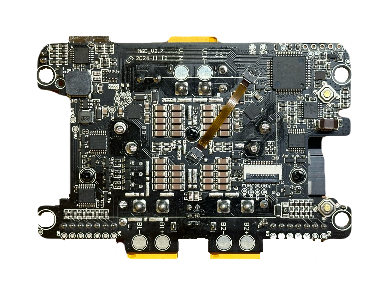
The M6D Board by ToolKitRC is a versatile development board designed for prototyping and testing electronic circuits. It features a powerful microcontroller, multiple input/output interfaces, and connectivity options, making it an ideal choice for embedded systems development. The M6D Board is suitable for hobbyists, students, and professionals working on projects ranging from IoT devices to robotics and automation.
Explore Projects Built with M6D Board

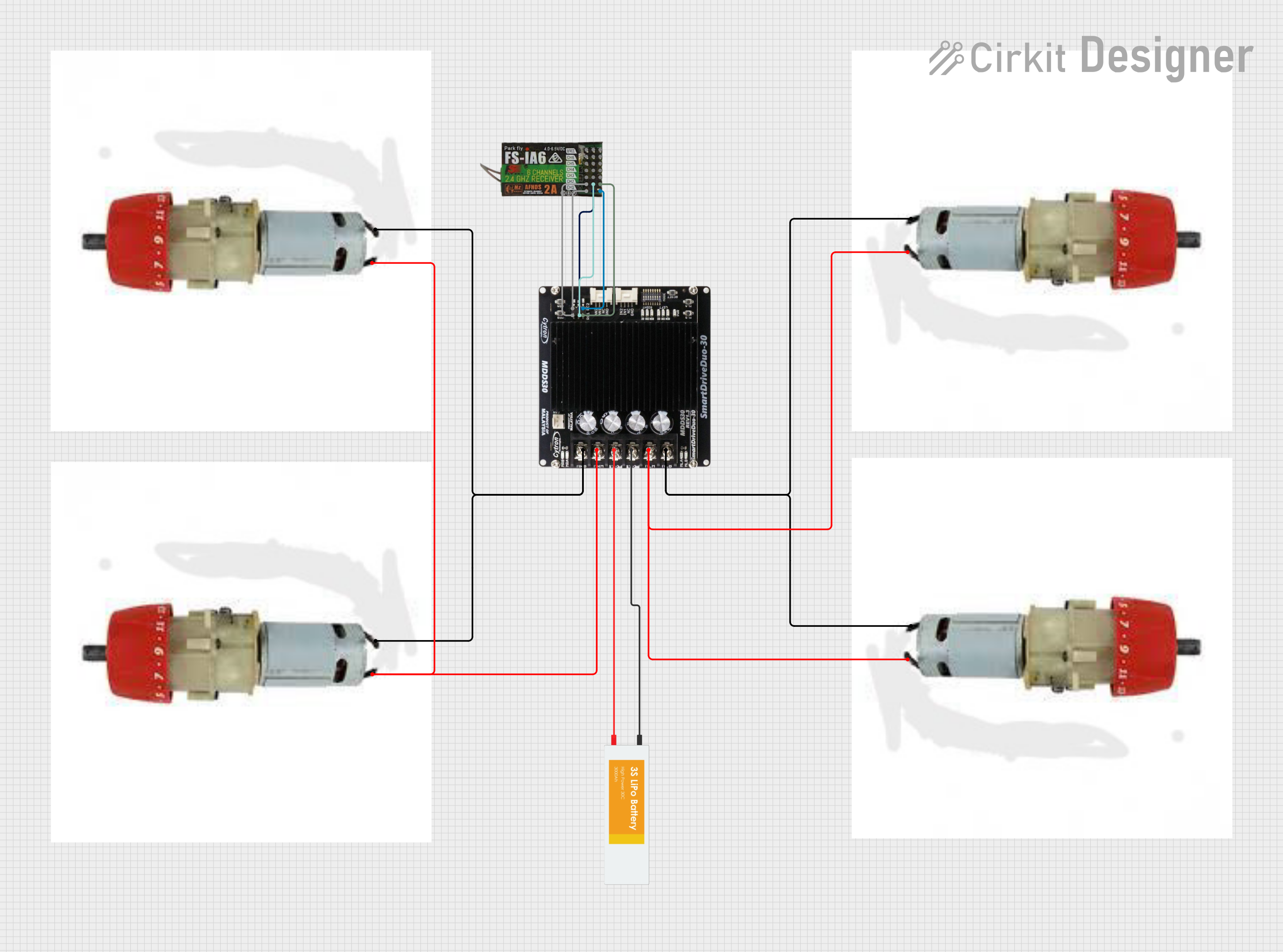
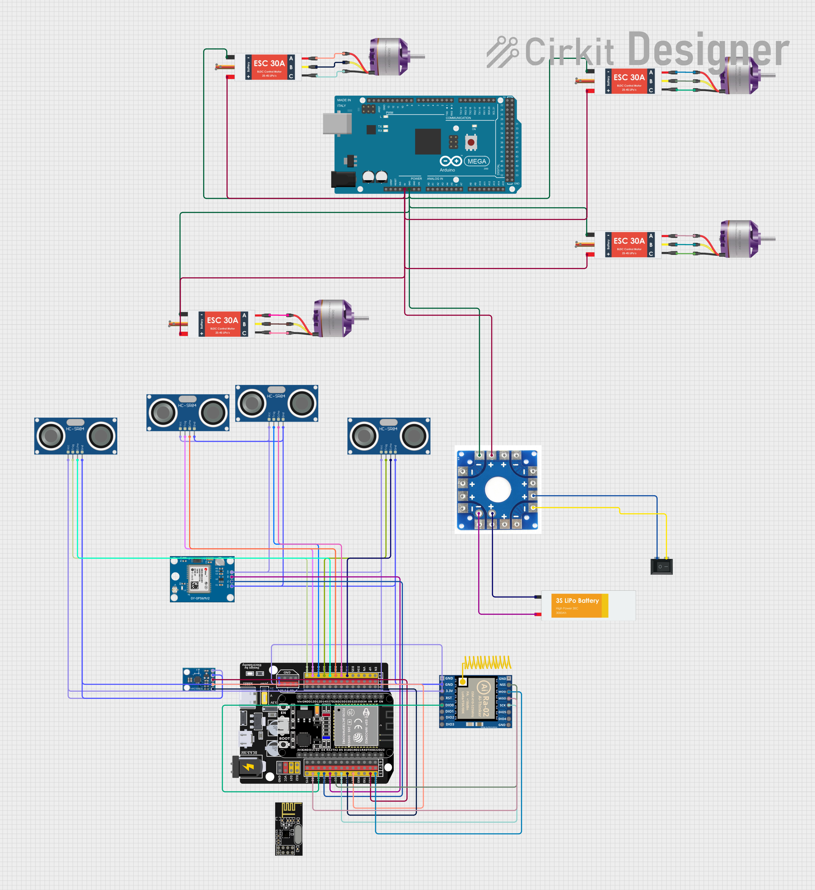

Explore Projects Built with M6D Board
Common Applications and Use Cases
- Prototyping embedded systems
- IoT (Internet of Things) device development
- Robotics and automation control
- Sensor data acquisition and processing
- Educational projects and learning microcontroller programming
Technical Specifications
The M6D Board is equipped with robust hardware and flexible interfaces to support a wide range of applications. Below are the key technical details:
General Specifications
| Parameter | Value |
|---|---|
| Microcontroller | ARM Cortex-M4 (32-bit) |
| Operating Voltage | 3.3V |
| Input Voltage Range | 5V - 12V |
| Digital I/O Pins | 20 |
| Analog Input Pins | 6 |
| PWM Output Pins | 8 |
| Communication Interfaces | UART, I2C, SPI, CAN |
| Flash Memory | 512 KB |
| SRAM | 128 KB |
| Clock Speed | 72 MHz |
| Connectivity Options | USB-C, Bluetooth (optional) |
| Dimensions | 60mm x 40mm |
Pin Configuration and Descriptions
The M6D Board features a 40-pin header for interfacing with external components. Below is the pinout description:
| Pin Number | Pin Name | Description |
|---|---|---|
| 1 | VIN | Input voltage (5V-12V) |
| 2 | GND | Ground |
| 3 | 3.3V | 3.3V output for powering peripherals |
| 4 | 5V | 5V output for powering peripherals |
| 5-14 | D0-D9 | Digital I/O pins |
| 15-20 | A0-A5 | Analog input pins |
| 21-28 | PWM0-PWM7 | PWM output pins |
| 29 | TX | UART Transmit |
| 30 | RX | UART Receive |
| 31-32 | SCL, SDA | I2C Clock and Data |
| 33-34 | MOSI, MISO | SPI Master Out, Slave In / Master In, Slave Out |
| 35 | SCK | SPI Clock |
| 36 | CANH | CAN Bus High |
| 37 | CANL | CAN Bus Low |
| 38 | RST | Reset pin |
| 39 | BOOT | Bootloader mode selection |
| 40 | NC | Not connected |
Usage Instructions
The M6D Board is designed to be user-friendly and adaptable to various projects. Follow the steps below to get started:
Basic Setup
Powering the Board:
- Connect the board to a power source using the USB-C port or the VIN pin (5V-12V).
- Ensure the power supply is stable to avoid damaging the board.
Programming the Board:
- Use a USB-C cable to connect the M6D Board to your computer.
- Install the necessary drivers and development environment (e.g., Arduino IDE or STM32CubeIDE).
- Select the appropriate microcontroller and port in your IDE.
Connecting Peripherals:
- Use the digital, analog, and communication pins to interface with sensors, actuators, and other devices.
- Refer to the pin configuration table for proper connections.
Example: Blinking an LED with Arduino IDE
The following example demonstrates how to blink an LED connected to pin D2 of the M6D Board:
// Example: Blinking an LED on the M6D Board
// Connect an LED to pin D2 with a 220-ohm resistor in series.

void setup() {
  pinMode(2, OUTPUT); // Set pin D2 as an output
}

void loop() {
  digitalWrite(2, HIGH); // Turn the LED on
  delay(1000);           // Wait for 1 second
  digitalWrite(2, LOW);  // Turn the LED off
  delay(1000);           // Wait for 1 second
}
Important Considerations
- Voltage Levels: Ensure that all connected peripherals operate within the board's voltage range (3.3V or 5V).
- Pin Current Limits: Do not exceed the maximum current rating of 20mA per pin to avoid damage.
- Static Protection: Handle the board with care to prevent electrostatic discharge (ESD).
Troubleshooting and FAQs
Common Issues and Solutions
The board is not detected by the computer:
- Ensure the USB-C cable is properly connected and functional.
- Check if the necessary drivers are installed.
- Try using a different USB port or cable.
The program does not upload to the board:
- Verify that the correct microcontroller and port are selected in the IDE.
- Press the RESET button before uploading the program.
- Check for any syntax errors in the code.
Peripherals are not responding:
- Double-check the wiring and connections.
- Ensure the peripherals are powered correctly.
- Use a multimeter to verify voltage levels at the pins.
FAQs
Q: Can the M6D Board be powered via the USB-C port?
A: Yes, the board can be powered through the USB-C port or the VIN pin (5V-12V).
Q: Does the M6D Board support wireless communication?
A: The board includes optional Bluetooth connectivity for wireless communication.
Q: What is the maximum clock speed of the microcontroller?
A: The microcontroller operates at a maximum clock speed of 72 MHz.
Q: Can I use the M6D Board with the Arduino IDE?
A: Yes, the M6D Board is compatible with the Arduino IDE. Install the necessary board definitions to get started.
By following this documentation, you can effectively utilize the M6D Board for your projects and troubleshoot common issues with ease.