How to Use Relay Omron MY2N: Examples, Pinouts, and Specs
Introduction
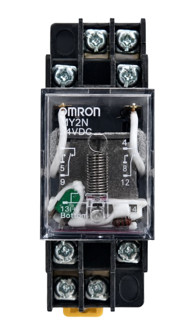
The Omron MY2N is a general-purpose electromagnetic relay with a Double Pole Double Throw (DPDT) configuration. It is designed to switch high currents and voltages while maintaining a compact and reliable form factor. This relay is widely used in automation, industrial control systems, and general-purpose switching applications. Its high durability and dependable performance make it a popular choice for engineers and hobbyists alike.
Explore Projects Built with Relay Omron MY2N


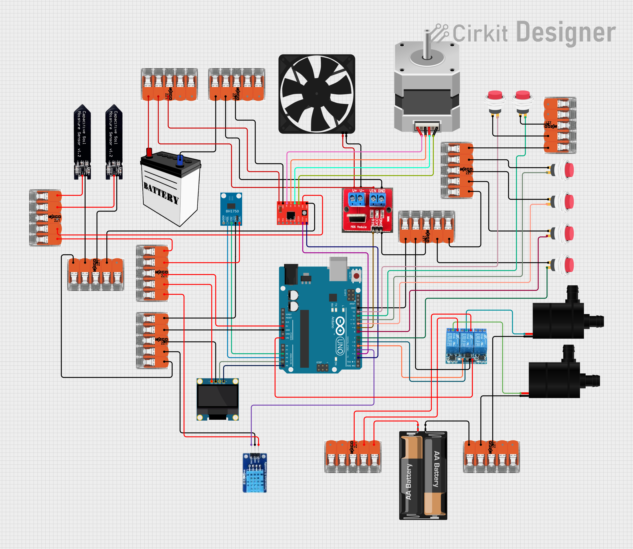
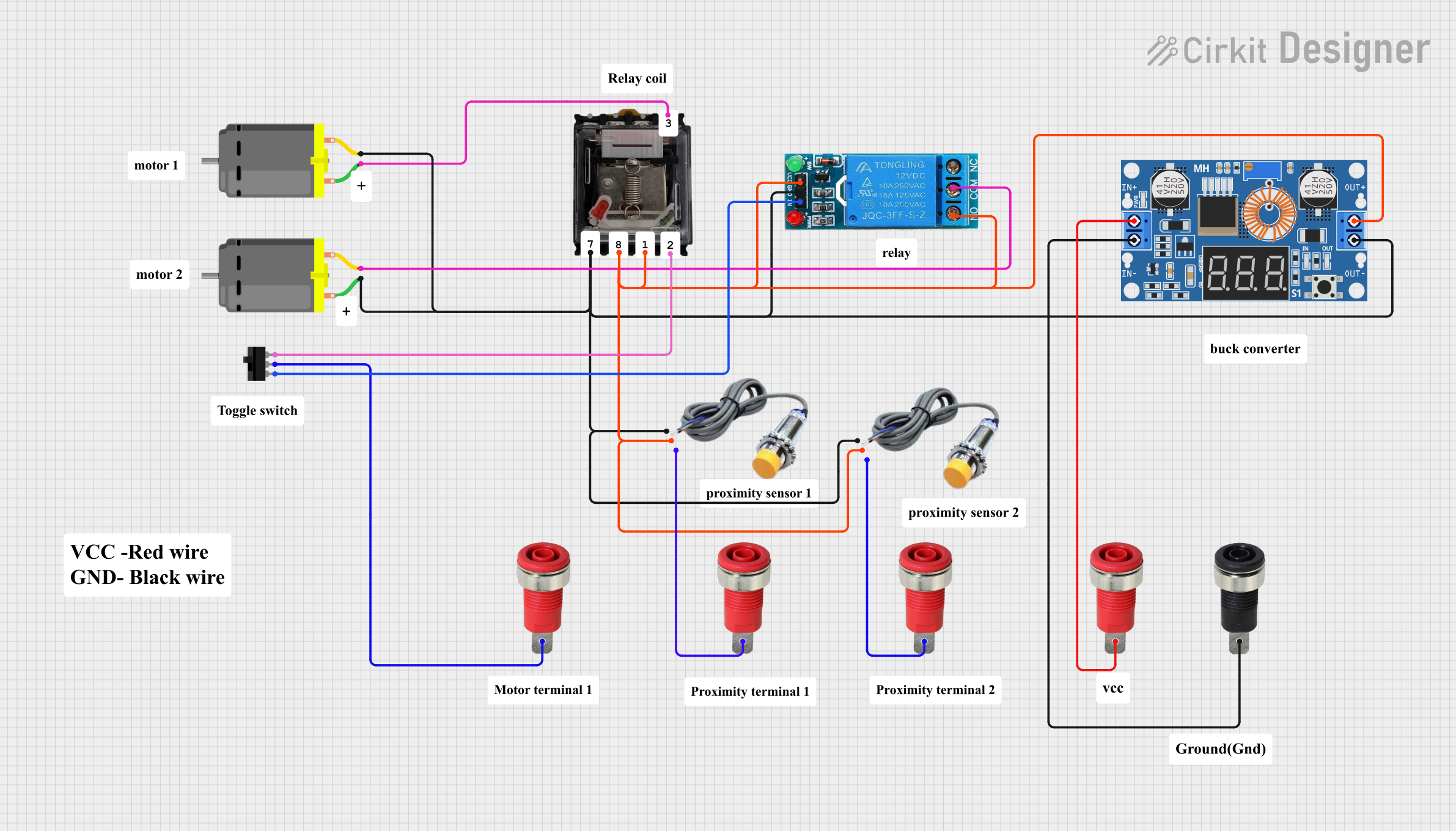
Explore Projects Built with Relay Omron MY2N
Common Applications
- Industrial automation and control systems
- Motor control circuits
- Signal switching in electronic devices
- Home automation projects
- Power distribution and load management
Technical Specifications
Below are the key technical details of the Omron MY2N relay:
| Parameter | Value |
|---|---|
| Coil Voltage | 6V, 12V, 24V, 48V, 110V, 220V DC/AC |
| Contact Configuration | DPDT (Double Pole Double Throw) |
| Contact Rating | 5A at 250VAC / 30VDC |
| Coil Resistance | Varies by coil voltage (e.g., 160Ω for 24V DC) |
| Operating Time | Approx. 20 ms |
| Release Time | Approx. 20 ms |
| Insulation Resistance | 100 MΩ minimum at 500VDC |
| Dielectric Strength | 2000VAC between coil and contacts |
| Mechanical Durability | 50 million operations |
| Electrical Durability | 500,000 operations (at rated load) |
| Ambient Operating Temperature | -55°C to 70°C |
| Dimensions | 28 x 21.5 x 36 mm |
Pin Configuration and Descriptions
The Omron MY2N relay has 8 pins, which are configured as follows:
| Pin Number | Description |
|---|---|
| 1 | Coil Terminal 1 |
| 2 | Coil Terminal 2 |
| 3 | Common Terminal for Pole 1 (COM1) |
| 4 | Normally Open Contact for Pole 1 (NO1) |
| 5 | Normally Closed Contact for Pole 1 (NC1) |
| 6 | Common Terminal for Pole 2 (COM2) |
| 7 | Normally Open Contact for Pole 2 (NO2) |
| 8 | Normally Closed Contact for Pole 2 (NC2) |
Usage Instructions
How to Use the Omron MY2N in a Circuit
- Power the Coil: Connect the relay's coil terminals (pins 1 and 2) to a DC or AC voltage source that matches the relay's rated coil voltage. Ensure the power supply can provide sufficient current to energize the coil.
- Connect the Load:
- For Pole 1: Connect the load to the common terminal (pin 3) and either the normally open (pin 4) or normally closed (pin 5) contact, depending on the desired switching behavior.
- For Pole 2: Similarly, connect the load to the common terminal (pin 6) and either the normally open (pin 7) or normally closed (pin 8) contact.
- Switching Behavior: When the coil is energized, the normally open (NO) contacts close, and the normally closed (NC) contacts open. When the coil is de-energized, the contacts return to their default state.
Important Considerations
- Flyback Diode: When using the relay with a DC coil, always connect a flyback diode across the coil terminals to protect the driving circuit from voltage spikes caused by the collapsing magnetic field.
- Driving the Relay: Use a transistor or MOSFET to drive the relay if the control signal cannot provide sufficient current. A base resistor is required when using a BJT transistor.
- Isolation: Ensure proper electrical isolation between the control circuit and the load circuit to prevent damage to sensitive components.
- Contact Ratings: Do not exceed the relay's contact ratings to avoid overheating or damage.
Example: Connecting the Omron MY2N to an Arduino UNO
Below is an example of how to control the Omron MY2N relay using an Arduino UNO:
Circuit Diagram
- Connect pin 1 of the relay coil to the collector of an NPN transistor (e.g., 2N2222).
- Connect pin 2 of the relay coil to the Arduino's GND.
- Place a flyback diode (e.g., 1N4007) across the coil terminals, with the cathode connected to pin 1.
- Connect the emitter of the transistor to GND.
- Connect the base of the transistor to an Arduino digital pin (e.g., pin 7) through a 1kΩ resistor.
- Connect the load to the relay's common and normally open contacts.
Arduino Code
// Define the relay control pin
const int relayPin = 7;

void setup() {
  pinMode(relayPin, OUTPUT); // Set the relay pin as an output
  digitalWrite(relayPin, LOW); // Ensure the relay is off at startup
}

void loop() {
  digitalWrite(relayPin, HIGH); // Turn the relay on
  delay(1000); // Keep the relay on for 1 second
  digitalWrite(relayPin, LOW); // Turn the relay off
  delay(1000); // Keep the relay off for 1 second
}
Troubleshooting and FAQs
Common Issues
Relay Not Switching:
- Cause: Insufficient voltage or current to the coil.
- Solution: Verify the power supply voltage and current match the relay's specifications.
Chattering or Unstable Operation:
- Cause: Noise or insufficient drive current.
- Solution: Use a decoupling capacitor near the relay coil and ensure the driving circuit provides adequate current.
Contacts Not Conducting Properly:
- Cause: Contacts may be worn or damaged.
- Solution: Check the contact surfaces and replace the relay if necessary.
Arduino Not Controlling the Relay:
- Cause: Incorrect wiring or missing flyback diode.
- Solution: Double-check the wiring and ensure a flyback diode is installed.
FAQs
Q: Can the Omron MY2N relay handle AC loads?
A: Yes, the relay can handle AC loads up to 250VAC, provided the current does not exceed 5A.
Q: Is the relay suitable for high-frequency switching?
A: No, the Omron MY2N is not designed for high-frequency switching. It is best suited for low to moderate switching frequencies.
Q: Can I use the relay without a transistor driver?
A: Only if the control signal can provide sufficient current to energize the coil. Otherwise, a transistor or MOSFET driver is recommended.
Q: What is the purpose of the flyback diode?
A: The flyback diode protects the driving circuit from voltage spikes generated when the relay coil is de-energized.