How to Use NavIC GPS: Examples, Pinouts, and Specs
Introduction
NavIC GPS, developed by the Indian Space Research Organisation (ISRO), is a regional satellite navigation system designed to provide accurate position information services. NavIC, short for "Navigation with Indian Constellation," is tailored to meet the positioning, navigation, and timing requirements of users in India and the surrounding region. It offers dual-frequency operation (L5 and S-band) for enhanced accuracy and reliability.
Explore Projects Built with NavIC GPS


Explore Projects Built with NavIC GPS
Common Applications and Use Cases
- Navigation: Used in vehicles, smartphones, and other devices for precise location tracking.
- Disaster Management: Assists in search and rescue operations during natural disasters.
- Agriculture: Enables precision farming by providing accurate geolocation data.
- Surveying and Mapping: Used in geodetic surveys and geographic information systems (GIS).
- Marine and Aviation: Supports navigation for ships and aircraft in the region.
Technical Specifications
NavIC GPS modules are typically integrated into devices as a receiver chip or module. Below are the key technical details:
Key Technical Details
- Frequency Bands: L5 (1176.45 MHz) and S-band (2492.028 MHz)
- Position Accuracy: < 5 meters (in India and surrounding regions)
- Coverage Area: India and a region extending up to 1,500 km beyond its borders
- Signal Types: Standard Positioning Service (SPS) and Restricted Service (RS)
- Power Supply: 3.3V to 5V (varies by module)
- Operating Temperature: -40°C to +85°C
- Interface: UART, I2C, or SPI (depending on the module)
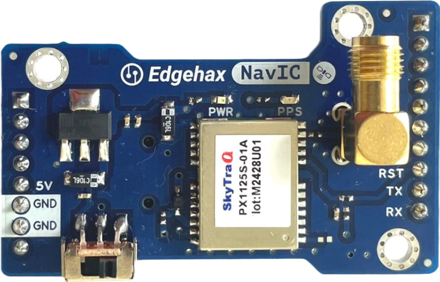
Pin Configuration and Descriptions
Below is an example pinout for a typical NavIC GPS module:
| Pin Number | Pin Name | Description |
|---|---|---|
| 1 | VCC | Power supply input (3.3V to 5V) |
| 2 | GND | Ground |
| 3 | TX | UART Transmit pin (data output) |
| 4 | RX | UART Receive pin (data input) |
| 5 | PPS | Pulse Per Second output for timing applications |
| 6 | EN | Enable pin to turn the module on/off |
| 7 | SDA | I2C Data line (optional, for I2C communication) |
| 8 | SCL | I2C Clock line (optional, for I2C communication) |
Note: Pin configuration may vary depending on the specific NavIC GPS module. Always refer to the manufacturer's datasheet for exact details.
Usage Instructions
How to Use the Component in a Circuit
- Power Supply: Connect the VCC pin to a regulated 3.3V or 5V power source and the GND pin to the ground.
- Data Communication: Use the TX and RX pins for UART communication with a microcontroller or computer. For I2C communication, connect the SDA and SCL pins to the corresponding pins on the microcontroller.
- Antenna Connection: Attach an external active antenna to the module's antenna port for better signal reception.
- Enable Pin: If the module has an EN pin, ensure it is pulled high to enable the module.
- Pulse Per Second (PPS): Use the PPS pin for precise timing applications, if required.
Important Considerations and Best Practices
- Antenna Placement: Place the antenna in an open area with a clear view of the sky for optimal signal reception.
- Power Supply: Use a stable and noise-free power source to avoid interference with the GPS signals.
- Baud Rate: Configure the UART baud rate (commonly 9600 bps) to match the module's default settings.
- Firmware Updates: Check for firmware updates from the manufacturer to ensure compatibility and improved performance.
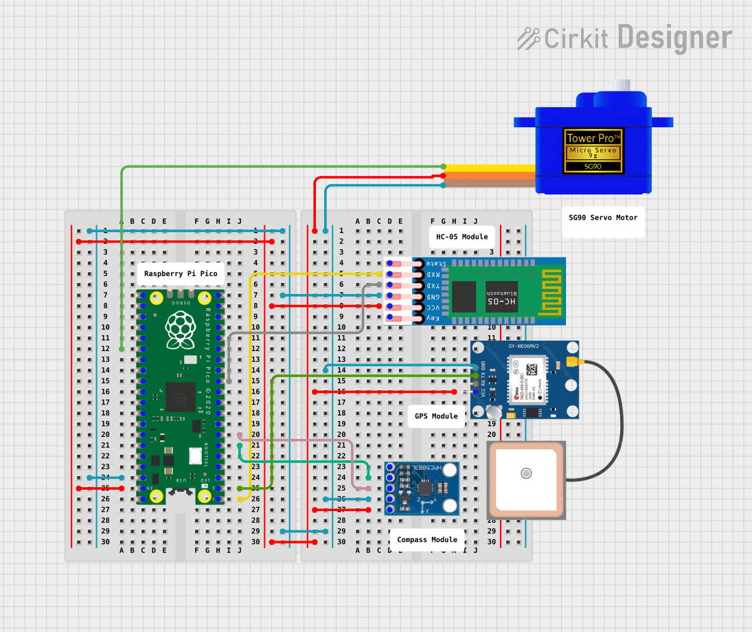
Example: Connecting NavIC GPS to Arduino UNO
Below is an example of how to interface a NavIC GPS module with an Arduino UNO using UART communication:
#include <SoftwareSerial.h>

// Define RX and TX pins for SoftwareSerial
SoftwareSerial navicGPS(4, 3); // RX = Pin 4, TX = Pin 3

void setup() {
  Serial.begin(9600);          // Initialize Serial Monitor at 9600 bps
  navicGPS.begin(9600);        // Initialize NavIC GPS module at 9600 bps
  Serial.println("NavIC GPS Module Initialized");
}

void loop() {
  // Check if data is available from the GPS module
  if (navicGPS.available()) {
    char c = navicGPS.read();  // Read one character from the GPS module
    Serial.print(c);           // Print the character to the Serial Monitor
  }
}
Note: Ensure the RX and TX pins of the GPS module are connected to the correct pins on the Arduino UNO. Use a level shifter if the GPS module operates at 3.3V logic levels.
Troubleshooting and FAQs
Common Issues and Solutions
No GPS Signal Detected:
- Cause: Poor antenna placement or obstruction.
- Solution: Place the antenna in an open area with a clear view of the sky.
Incorrect Data Output:
- Cause: Mismatched baud rate or incorrect wiring.
- Solution: Verify the baud rate and check the connections between the module and the microcontroller.
Module Not Powering On:
- Cause: Insufficient power supply or incorrect wiring.
- Solution: Ensure the power supply meets the module's voltage and current requirements.
Intermittent Signal Loss:
- Cause: Electromagnetic interference or poor antenna quality.
- Solution: Use a high-quality active antenna and minimize nearby sources of interference.
FAQs
Q: Can NavIC GPS work indoors?
A: NavIC GPS is designed for outdoor use. Signal reception indoors may be weak or unavailable.Q: Is NavIC GPS compatible with other GNSS systems like GPS or GLONASS?
A: Many NavIC GPS modules support multi-GNSS operation, allowing them to work with GPS, GLONASS, and Galileo for improved accuracy.Q: What is the typical time to first fix (TTFF) for NavIC GPS?
A: The TTFF is typically 30-60 seconds for a cold start and 1-5 seconds for a hot start.Q: Can NavIC GPS be used for timing applications?
A: Yes, the PPS pin provides precise timing signals for synchronization purposes.
By following this documentation, users can effectively integrate and utilize the NavIC GPS module in their projects.