How to Use Esp32-Cam WROVER: Examples, Pinouts, and Specs
Introduction
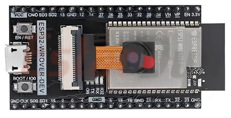
The ESP32-CAM WROVER is a low-cost development board that combines the powerful ESP32 chip with integrated Wi-Fi and Bluetooth capabilities, along with a camera module. This compact and versatile board is ideal for IoT applications, enabling users to capture images, stream video wirelessly, and perform edge computing tasks. Its small form factor and rich feature set make it a popular choice for projects such as home automation, surveillance systems, and AI-powered image recognition.
Explore Projects Built with Esp32-Cam WROVER

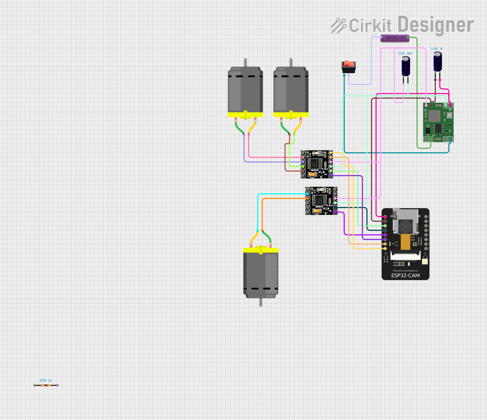
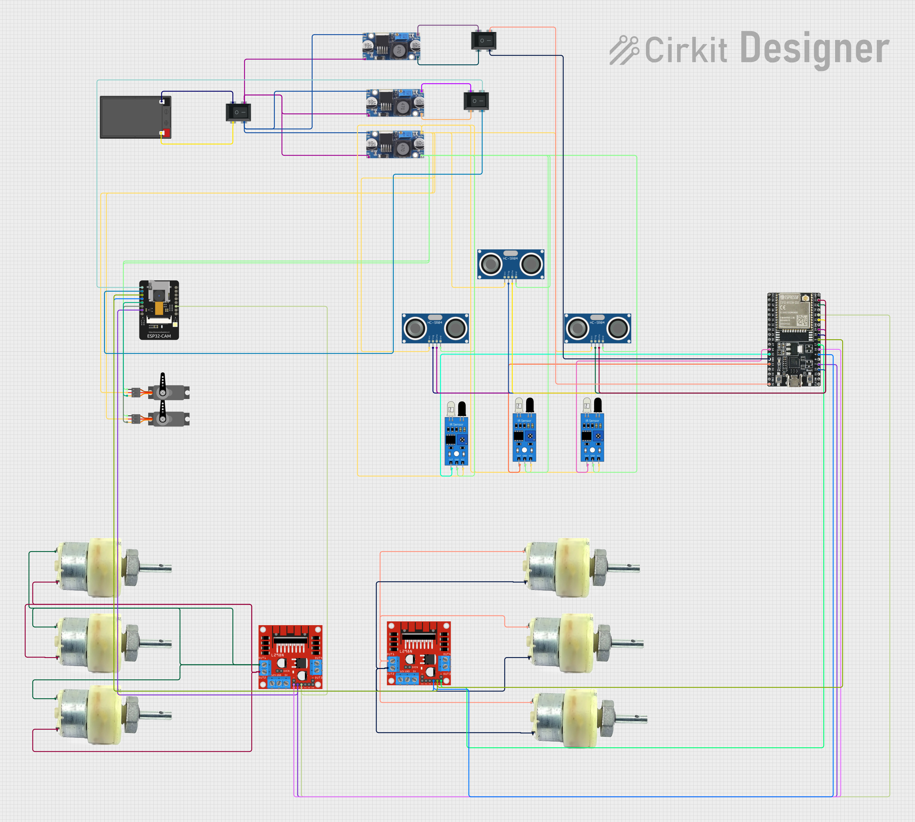
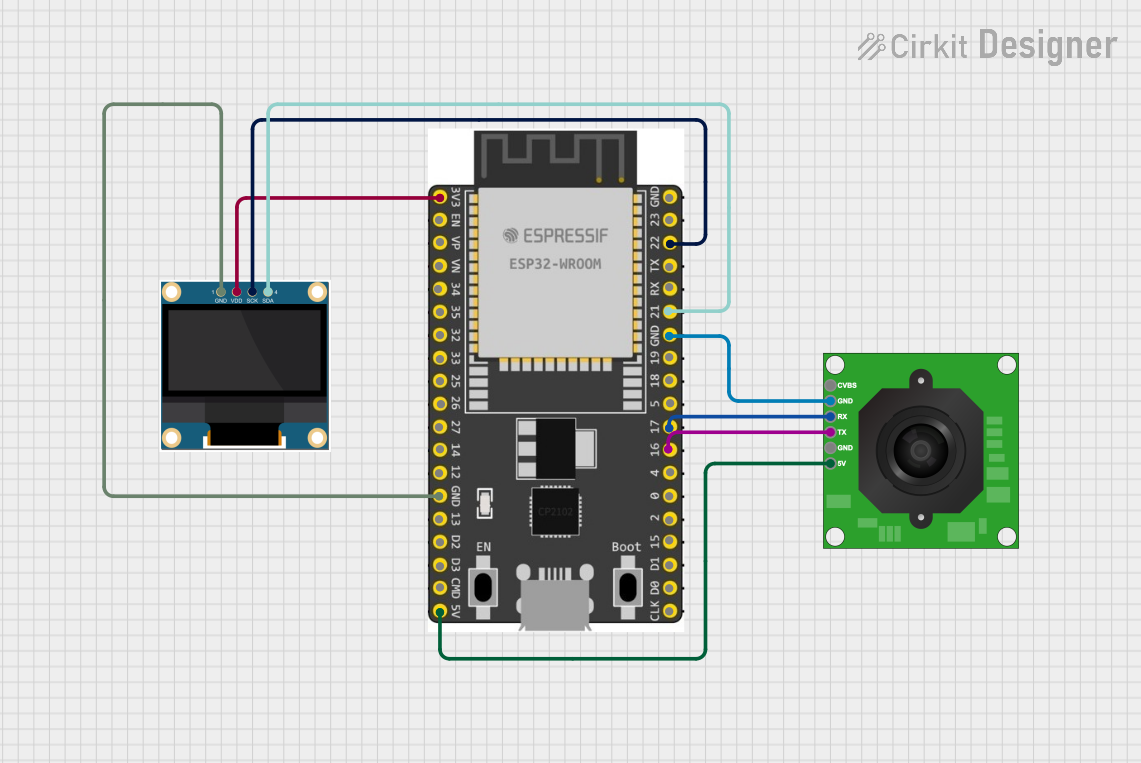
Explore Projects Built with Esp32-Cam WROVER
Common Applications and Use Cases
- Wireless video streaming and image capture
- Home security and surveillance systems
- Smart doorbells and intercoms
- AI-based image recognition and processing
- IoT-enabled monitoring systems
- Robotics and drone vision systems
Technical Specifications
The ESP32-CAM WROVER is equipped with a range of features that make it suitable for various applications. Below are its key technical specifications:
Key Technical Details
- Microcontroller: ESP32-D0WDQ6 with dual-core Xtensa® 32-bit LX6 processor
- Clock Speed: Up to 240 MHz
- Flash Memory: 4 MB
- PSRAM: 8 MB
- Wi-Fi: 802.11 b/g/n
- Bluetooth: BLE and Bluetooth 4.2
- Camera Module: OV2640 (2 MP resolution)
- Operating Voltage: 3.3V
- Power Supply: 5V (via micro-USB or external source)
- GPIO Pins: 9 available for user applications
- Interfaces: UART, SPI, I2C, PWM, ADC, DAC
- Dimensions: 27 mm x 40.5 mm
Pin Configuration and Descriptions
The ESP32-CAM WROVER has a total of 16 pins. Below is the pinout and description:
| Pin | Name | Description |
|---|---|---|
| 1 | GND | Ground pin |
| 2 | 5V | Power input (5V) |
| 3 | 3.3V | Power output (3.3V) |
| 4 | GPIO0 | General-purpose I/O; used for boot mode selection |
| 5 | GPIO1 (U0TXD) | UART0 TX pin |
| 6 | GPIO3 (U0RXD) | UART0 RX pin |
| 7 | GPIO4 | General-purpose I/O; supports PWM, ADC, etc. |
| 8 | GPIO12 | General-purpose I/O; used for SD card data |
| 9 | GPIO13 | General-purpose I/O; used for SD card data |
| 10 | GPIO14 | General-purpose I/O; used for SD card clock |
| 11 | GPIO15 | General-purpose I/O; used for SD card command |
| 12 | GPIO16 | General-purpose I/O; supports PWM, ADC, etc. |
| 13 | GPIO2 | General-purpose I/O; connected to the onboard LED |
| 14 | GPIO21 | General-purpose I/O; supports I2C SDA |
| 15 | GPIO22 | General-purpose I/O; supports I2C SCL |
| 16 | RESET | Reset pin; used to restart the board |
Usage Instructions
The ESP32-CAM WROVER can be used in a variety of projects. Below are the steps to get started and important considerations:
How to Use the ESP32-CAM WROVER in a Circuit
- Power the Board: Connect the 5V pin to a 5V power source or use the micro-USB port.
- Connect GPIO0 for Programming: To upload code, connect GPIO0 to GND and reset the board. After programming, disconnect GPIO0 from GND.
- Camera Module: Ensure the OV2640 camera module is securely connected to the board.
- Programming: Use the Arduino IDE or ESP-IDF to upload code. Select "AI-Thinker ESP32-CAM" as the board in the Arduino IDE.
- Serial Communication: Connect the UART pins (U0TXD and U0RXD) to a USB-to-serial adapter for programming and debugging.
Important Considerations and Best Practices
- Power Supply: Ensure a stable 5V power supply. Insufficient power can cause the board to reset or fail to boot.
- Heat Management: The ESP32 chip can get warm during operation. Consider adding a heatsink for prolonged use.
- Antenna: The onboard PCB antenna provides decent range, but for better performance, use an external antenna (requires soldering).
- Boot Mode: Always disconnect GPIO0 from GND after uploading code to avoid boot issues.
- Camera Orientation: Ensure the camera module is properly aligned and not obstructed.
Example Code for Arduino IDE
Below is an example code snippet to capture an image and stream video using the ESP32-CAM WROVER:
#include <WiFi.h>
#include <esp_camera.h>

// Replace with your Wi-Fi credentials
const char* ssid = "Your_SSID";
const char* password = "Your_PASSWORD";

void startCameraServer();

void setup() {
  Serial.begin(115200);

  // Configure the camera
  camera_config_t config;
  config.ledc_channel = LEDC_CHANNEL_0;
  config.ledc_timer = LEDC_TIMER_0;
  config.pin_d0 = 5;
  config.pin_d1 = 18;
  config.pin_d2 = 19;
  config.pin_d3 = 21;
  config.pin_d4 = 36;
  config.pin_d5 = 39;
  config.pin_d6 = 34;
  config.pin_d7 = 35;
  config.pin_xclk = 0;
  config.pin_pclk = 22;
  config.pin_vsync = 25;
  config.pin_href = 23;
  config.pin_sscb_sda = 26;
  config.pin_sscb_scl = 27;
  config.pin_pwdn = -1;
  config.pin_reset = -1;
  config.xclk_freq_hz = 20000000;
  config.pixel_format = PIXFORMAT_JPEG;

  // Initialize the camera
  if (!esp_camera_init(&config)) {
    Serial.println("Camera initialized successfully");
  } else {
    Serial.println("Camera initialization failed");
    return;
  }

  // Connect to Wi-Fi
  WiFi.begin(ssid, password);
  while (WiFi.status() != WL_CONNECTED) {
    delay(500);
    Serial.print(".");
  }
  Serial.println("\nWi-Fi connected");

  // Start the camera server
  startCameraServer();
}

void loop() {
  // Main loop does nothing; camera server handles requests
}
Troubleshooting and FAQs
Common Issues and Solutions
Board Not Booting:
- Ensure GPIO0 is disconnected from GND after programming.
- Verify the power supply provides a stable 5V.
Camera Initialization Failed:
- Check the camera module connection.
- Ensure the correct camera model is selected in the code (e.g., OV2640).
Wi-Fi Connection Issues:
- Double-check the SSID and password in the code.
- Ensure the router is within range of the ESP32-CAM.
Overheating:
- Add a heatsink to the ESP32 chip if it gets too warm during operation.
FAQs
Q: Can I use the ESP32-CAM without a camera?
A: Yes, the ESP32-CAM can function as a standard ESP32 development board without the camera.Q: How do I reset the board?
A: Use the RESET pin or press the onboard reset button (if available).Q: Can I use an SD card with the ESP32-CAM?
A: Yes, the board supports SD cards via GPIO12, GPIO13, GPIO14, and GPIO15.Q: What is the maximum resolution of the camera?
A: The OV2640 camera supports a maximum resolution of 1600x1200 pixels (UXGA).