How to Use brushless esc: Examples, Pinouts, and Specs
Introduction
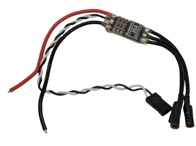
A Brushless Electronic Speed Controller (ESC) is a critical component used to regulate the speed, direction, and braking of brushless motors. It achieves this by converting direct current (DC) from a power source into a three-phase alternating current (AC) to drive the motor. Brushless ESCs are widely used in applications requiring precise motor control, such as drones, remote-controlled (RC) vehicles, electric skateboards, and robotics.
Explore Projects Built with brushless esc


Explore Projects Built with brushless esc
Common Applications:
- Drones and quadcopters for controlling propeller speed
- RC cars, boats, and planes for motor control
- Electric skateboards and scooters
- Robotics and industrial automation systems
Technical Specifications
Below are the general technical specifications for a typical brushless ESC. Note that specific values may vary depending on the model and manufacturer.
Key Technical Details:
- Input Voltage Range: 6V to 50V (commonly 2S to 12S LiPo batteries)
- Continuous Current Rating: 10A to 200A (depending on the model)
- Peak Current Rating: Typically 1.5x to 2x the continuous current rating
- Supported Motor Types: Brushless DC (BLDC) motors
- Control Signal Input: PWM (Pulse Width Modulation) signal, typically 1ms to 2ms pulse width
- BEC (Battery Eliminator Circuit): Optional, provides regulated voltage (e.g., 5V or 6V) for powering external devices like servos or microcontrollers
- Operating Temperature: -20°C to 85°C (varies by model)
- Protection Features: Overcurrent, overvoltage, thermal shutdown, and low-voltage cutoff
Pin Configuration and Descriptions:
The pin configuration of a brushless ESC typically includes the following connections:
| Pin Name | Description |
|---|---|
| Power Input (+/-) | Connects to the positive (+) and negative (-) terminals of the power source. |
| Motor Output (A, B, C) | Three-phase output terminals for connecting to the brushless motor. |
| Signal Input (PWM) | Receives the control signal (PWM) from a microcontroller or receiver. |
| BEC Output (+/-) | Provides regulated voltage (if available) for powering external devices. |
Usage Instructions
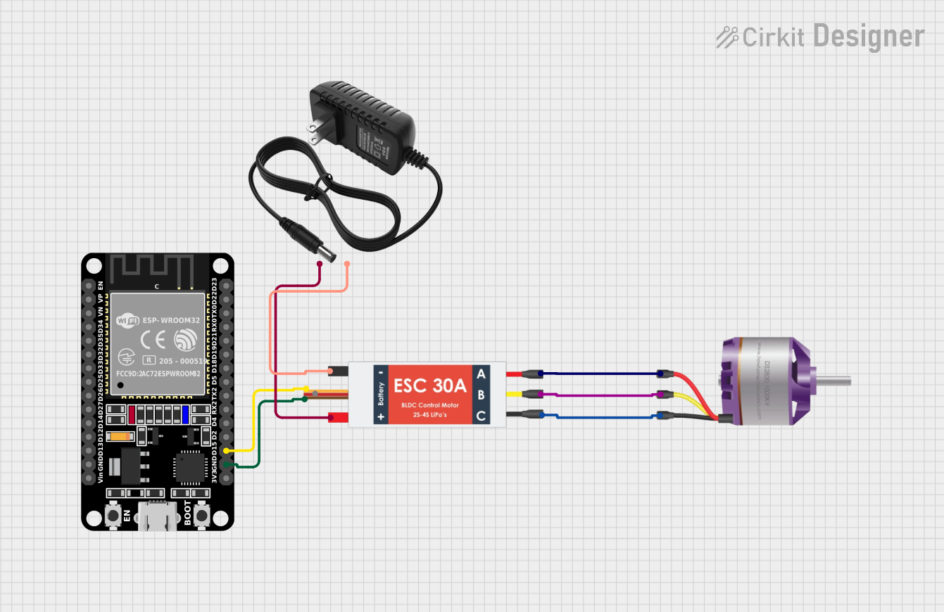
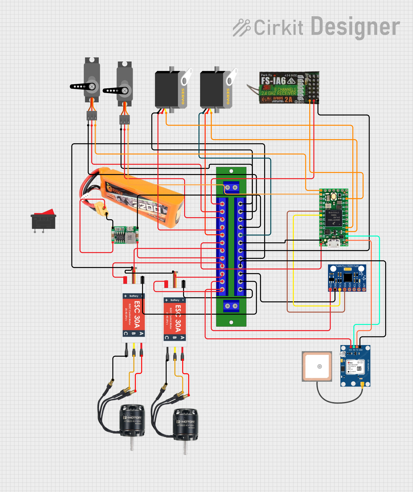
How to Use a Brushless ESC in a Circuit:
- Connect the Power Source: Attach the ESC's power input terminals to a compatible battery (e.g., LiPo). Ensure the voltage and current ratings match the ESC's specifications.
- Connect the Motor: Attach the three motor output wires (A, B, C) to the brushless motor. If the motor spins in the wrong direction, swap any two of the three wires.
- Connect the Signal Input: Use a PWM-capable device (e.g., an RC receiver or microcontroller) to send control signals to the ESC's signal input pin.
- Optional - Use the BEC Output: If the ESC has a built-in BEC, connect the BEC output to power external devices like servos or microcontrollers.
- Calibrate the ESC: Follow the manufacturer's instructions to calibrate the ESC for your specific transmitter or controller. This typically involves setting the throttle range.
Important Considerations:
- Cooling: Ensure proper airflow or heat dissipation to prevent the ESC from overheating during operation.
- Battery Compatibility: Use a battery with the correct voltage and discharge rating to avoid damaging the ESC or motor.
- Signal Quality: Ensure the PWM signal is clean and within the specified range (typically 1ms to 2ms pulse width).
- Startup Safety: Always test the ESC and motor in a safe environment to avoid accidents.
Example Code for Arduino UNO:
Below is an example of how to control a brushless ESC using an Arduino UNO:
#include <Servo.h> // Include the Servo library to generate PWM signals

Servo esc; // Create a Servo object to control the ESC

void setup() {
  esc.attach(9); // Attach the ESC signal wire to pin 9 on the Arduino
  esc.writeMicroseconds(1000); // Send minimum throttle signal (1ms pulse width)
  delay(2000); // Wait for 2 seconds to allow the ESC to initialize
}

void loop() {
  esc.writeMicroseconds(1500); // Set throttle to 50% (1.5ms pulse width)
  delay(5000); // Run the motor at 50% throttle for 5 seconds

  esc.writeMicroseconds(1000); // Set throttle to 0% (1ms pulse width)
  delay(5000); // Stop the motor for 5 seconds
}
Notes:
- Replace
9inesc.attach(9)with the appropriate pin number if using a different pin. - Adjust the
writeMicrosecondsvalues to control the motor speed (1000 = minimum, 2000 = maximum).
Troubleshooting and FAQs
Common Issues and Solutions:
Motor Does Not Spin:
- Cause: Incorrect wiring or no signal from the controller.
- Solution: Verify all connections, ensure the ESC is receiving a valid PWM signal, and check the battery voltage.
Motor Spins in the Wrong Direction:
- Cause: Incorrect wiring of the motor output terminals.
- Solution: Swap any two of the three motor wires (A, B, C).
ESC Overheats:
- Cause: Insufficient cooling or excessive current draw.
- Solution: Improve airflow around the ESC or use a higher-rated ESC.
ESC Beeps Continuously:
- Cause: Low battery voltage or no signal from the controller.
- Solution: Check the battery voltage and ensure the controller is sending a valid signal.
Motor Stutters or Jerks:
- Cause: Poor connections or incompatible motor/ESC pairing.
- Solution: Check all connections and ensure the motor and ESC are compatible.
FAQs:
Q: Can I use a brushless ESC with a brushed motor?
A: No, brushless ESCs are designed specifically for brushless motors. Use a brushed ESC for brushed motors.Q: How do I know if my ESC has a built-in BEC?
A: Check the manufacturer's specifications or look for a labeled output (e.g., 5V or 6V) on the ESC.Q: Can I control multiple ESCs with one microcontroller?
A: Yes, as long as the microcontroller has enough PWM-capable pins and processing power to handle multiple signals.Q: What happens if I exceed the ESC's current rating?
A: The ESC may overheat, shut down, or become permanently damaged. Always use an ESC with a current rating higher than the motor's maximum draw.
By following this documentation, you can effectively use a brushless ESC in your projects and troubleshoot common issues.