How to Use DFRobot Gravity Analog high Electrical Conductivity Sensor Meter K=10: Examples, Pinouts, and Specs
Introduction
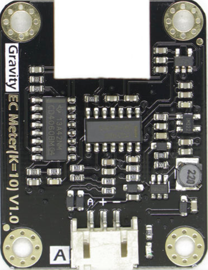
The DFRobot Gravity Analog High Electrical Conductivity Sensor Meter K=10 is a high-precision sensor designed to measure the electrical conductivity (EC) of liquids. It provides an analog output proportional to the conductivity level, making it ideal for applications requiring accurate water quality monitoring. With its robust design and high sensitivity, this sensor is particularly suited for use in industrial, agricultural, and environmental testing scenarios.
Explore Projects Built with DFRobot Gravity Analog high Electrical Conductivity Sensor Meter K=10
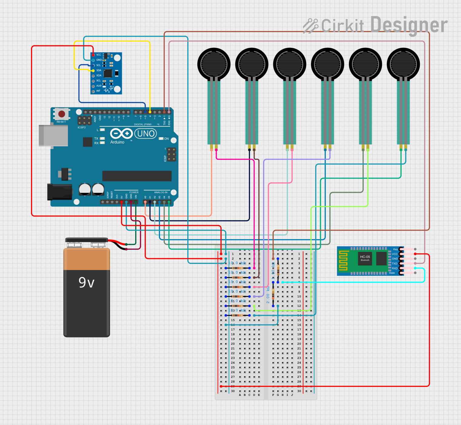
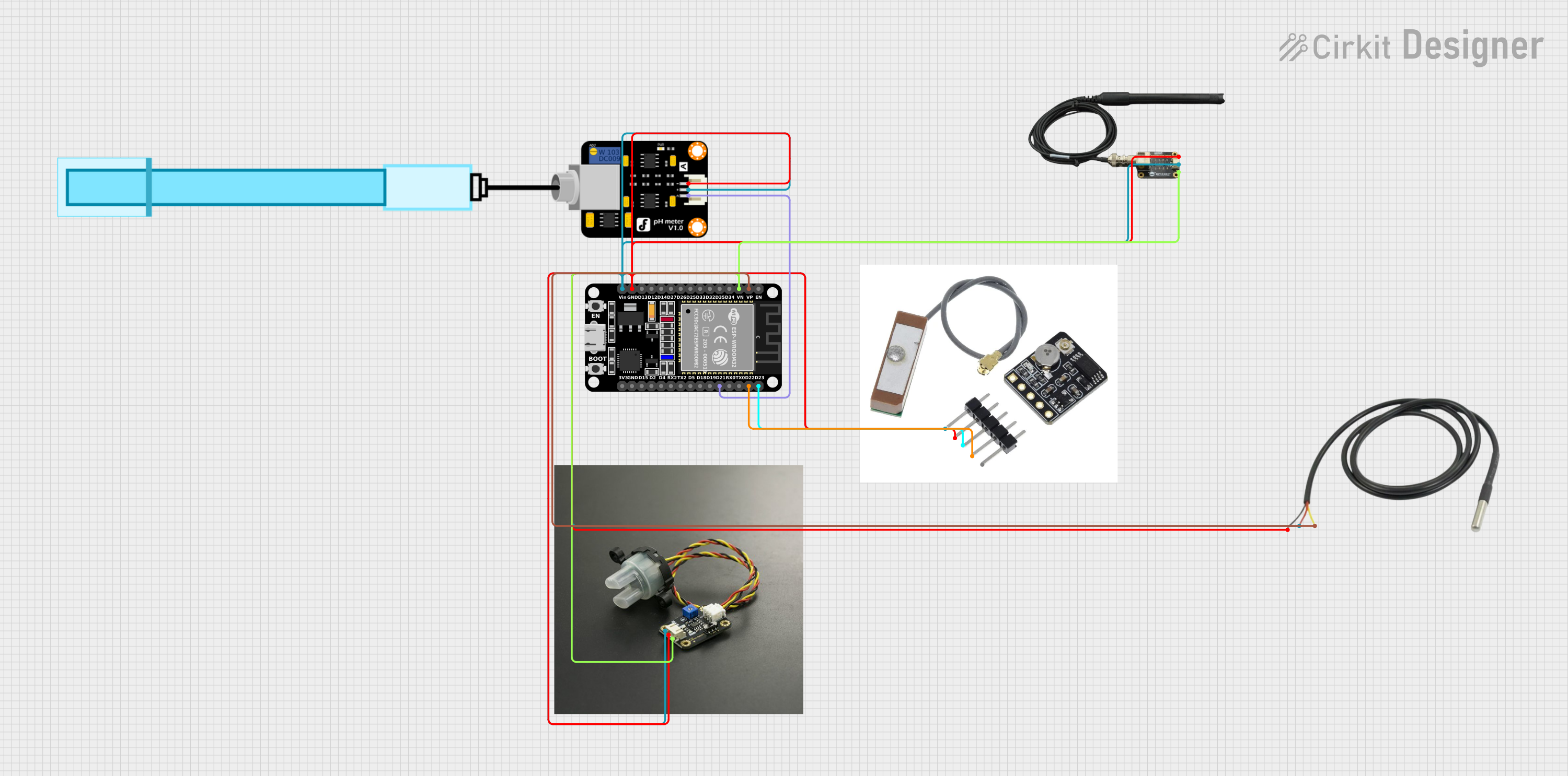
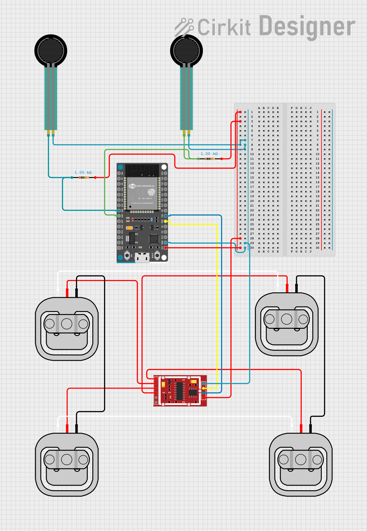

Explore Projects Built with DFRobot Gravity Analog high Electrical Conductivity Sensor Meter K=10
Common Applications
- Water quality monitoring in aquariums, hydroponics, and aquaculture
- Environmental testing for rivers, lakes, and groundwater
- Industrial process control and wastewater treatment
- Agricultural irrigation systems
Technical Specifications
Below are the key technical details and pin configuration for the sensor:
Key Technical Details
| Parameter | Specification |
|---|---|
| Operating Voltage | 3.3V - 5.5V |
| Output Signal | Analog voltage (0-3.4V) |
| Measurement Range | 0 - 200 mS/cm |
| Accuracy | ±2% F.S. |
| Temperature Compensation | Yes (10°C - 40°C) |
| Probe Constant (K) | K=10 |
| Cable Length | 1 meter |
| Interface Type | Gravity 3-pin interface |
| Dimensions | 42mm x 32mm |
Pin Configuration
The sensor uses a 3-pin Gravity interface for easy connection. Below is the pinout description:
| Pin Name | Description |
|---|---|
| VCC | Power supply (3.3V - 5.5V) |
| GND | Ground |
| AOUT | Analog output signal (0-3.4V) |
Usage Instructions
How to Use the Sensor in a Circuit
Connect the Sensor to a Microcontroller:
- Connect the VCC pin to the 5V or 3.3V power supply of your microcontroller.
- Connect the GND pin to the ground of your microcontroller.
- Connect the AOUT pin to an analog input pin on your microcontroller (e.g., A0 on an Arduino UNO).
Calibrate the Sensor:
- The sensor requires calibration to ensure accurate readings. Use a standard solution with a known conductivity value for calibration.
- Adjust the potentiometer on the sensor board to match the output voltage with the expected value for the calibration solution.
Read the Analog Output:
- The sensor outputs an analog voltage proportional to the conductivity of the liquid. Use the microcontroller's ADC (Analog-to-Digital Converter) to read the voltage and convert it to a conductivity value.
Important Considerations and Best Practices
- Temperature Compensation: The sensor includes basic temperature compensation for measurements between 10°C and 40°C. For more precise results, consider implementing additional compensation in your code.
- Probe Maintenance: Clean the probe regularly to prevent fouling, which can affect accuracy.
- Avoid Air Exposure: Do not expose the probe to air for extended periods, as this can damage the sensor.
- Use Proper Calibration Solutions: Always use high-quality calibration solutions with known conductivity values for accurate calibration.
Example Code for Arduino UNO
Below is an example of how to use the sensor with an Arduino UNO:
// DFRobot Gravity Analog High Electrical Conductivity Sensor Example
// Connect the sensor's AOUT pin to Arduino analog pin A0
// Ensure the sensor is properly calibrated before use

const int sensorPin = A0; // Analog pin connected to the sensor's AOUT pin
float voltage;            // Variable to store the sensor's output voltage
float conductivity;       // Variable to store the calculated conductivity

void setup() {
  Serial.begin(9600); // Initialize serial communication at 9600 baud
  pinMode(sensorPin, INPUT); // Set the sensor pin as input
}

void loop() {
  // Read the analog value from the sensor
  int sensorValue = analogRead(sensorPin);

  // Convert the analog value to voltage (assuming 5V reference)
  voltage = sensorValue * (5.0 / 1023.0);

  // Convert the voltage to conductivity (mS/cm)
  // This formula depends on the sensor's calibration and K constant
  conductivity = voltage * 100; // Example conversion factor (adjust as needed)

  // Print the results to the Serial Monitor
  Serial.print("Voltage: ");
  Serial.print(voltage);
  Serial.print(" V, Conductivity: ");
  Serial.print(conductivity);
  Serial.println(" mS/cm");

  delay(1000); // Wait 1 second before the next reading
}
Troubleshooting and FAQs
Common Issues and Solutions
No Output or Incorrect Readings:
- Cause: Loose or incorrect wiring.
- Solution: Double-check all connections, ensuring the VCC, GND, and AOUT pins are properly connected.
Inconsistent Readings:
- Cause: Fouled or dirty probe.
- Solution: Clean the probe with distilled water and a soft cloth. Avoid using abrasive materials.
Output Voltage Exceeds Expected Range:
- Cause: Calibration error or incorrect reference voltage.
- Solution: Recalibrate the sensor using a standard solution. Verify the microcontroller's ADC reference voltage.
Temperature Compensation Not Accurate:
- Cause: Extreme temperature variations.
- Solution: Implement additional temperature compensation in your code if operating outside the 10°C - 40°C range.
FAQs
Q: Can this sensor measure salinity?
A: Yes, salinity can be derived from conductivity measurements using appropriate conversion formulas.
Q: Is the sensor waterproof?
A: The probe is waterproof and designed for immersion in liquids. However, the sensor board is not waterproof and must be kept dry.
Q: How often should I calibrate the sensor?
A: Calibration frequency depends on usage. For critical applications, calibrate before each use. For general use, calibrate monthly or as needed.
Q: Can I use this sensor with a 3.3V microcontroller?
A: Yes, the sensor operates within a voltage range of 3.3V to 5.5V, making it compatible with 3.3V systems.