How to Use Pzem: Examples, Pinouts, and Specs
Introduction
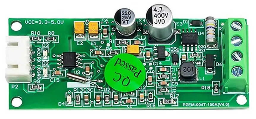
The PZEM is a multifunctional energy meter designed to measure key electrical parameters such as voltage, current, power, energy, and frequency in AC electrical circuits. It is widely used in applications requiring energy monitoring and management, such as home automation, industrial equipment monitoring, and renewable energy systems. Its compact design and ease of integration make it a popular choice for both hobbyists and professionals.
Common applications include:
- Monitoring household or industrial energy consumption.
- Measuring power usage in renewable energy systems (e.g., solar or wind setups).
- Integrating with microcontrollers like Arduino or Raspberry Pi for data logging and analysis.
- Overload protection and energy management in electrical systems.
Explore Projects Built with Pzem


Explore Projects Built with Pzem
Technical Specifications
The PZEM energy meter comes in various models (e.g., PZEM-004T, PZEM-017), but the following are general specifications for a typical PZEM module:
| Parameter | Specification |
|---|---|
| Voltage Range | 80V - 260V AC |
| Current Range | 0A - 100A (with external current transformer) |
| Power Range | 0W - 22kW |
| Energy Range | 0kWh - 9999kWh |
| Frequency Range | 45Hz - 65Hz |
| Communication Interface | UART (TTL level) |
| Power Supply | Self-powered (from measured circuit) |
| Accuracy | ±0.5% |
Pin Configuration
The PZEM module typically has a 4-pin interface for communication and power. Below is the pin configuration:
| Pin | Name | Description |
|---|---|---|
| 1 | VCC | Power supply for the module (5V DC) |
| 2 | GND | Ground connection |
| 3 | RX | UART Receive pin (connect to TX of microcontroller) |
| 4 | TX | UART Transmit pin (connect to RX of microcontroller) |
Usage Instructions
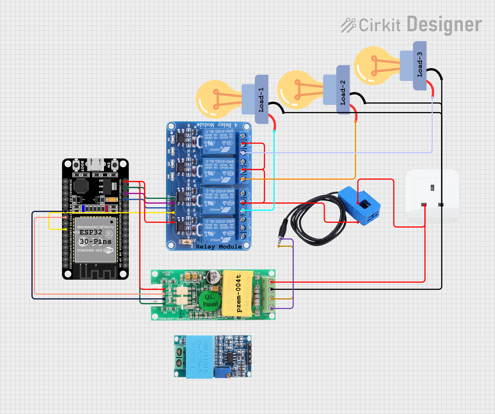
How to Use the PZEM in a Circuit
Connect the PZEM to the Measured Circuit:
- Connect the voltage input terminals of the PZEM to the AC circuit you want to monitor.
- Pass the live wire of the circuit through the external current transformer (CT) provided with the PZEM.
Power the Module:
- The PZEM is typically self-powered from the measured circuit. However, some models may require an external 5V DC supply via the VCC and GND pins.
Connect to a Microcontroller:
- Use the UART interface to connect the PZEM to a microcontroller like an Arduino UNO. Connect the RX pin of the PZEM to the TX pin of the Arduino, and the TX pin of the PZEM to the RX pin of the Arduino.
Install Required Libraries:
- For Arduino, use the "PZEM004T" library available in the Arduino IDE Library Manager.
Write and Upload Code:
- Use the example code below to read data from the PZEM and display it on the serial monitor.
Example Code for Arduino UNO
#include <PZEM004T.h> // Include the PZEM library

// Define the RX and TX pins for the PZEM module
#define PZEM_RX_PIN 10
#define PZEM_TX_PIN 11

// Create a PZEM object
PZEM004T pzem(PZEM_RX_PIN, PZEM_TX_PIN);

void setup() {
  Serial.begin(9600); // Initialize serial communication
  Serial.println("PZEM Energy Meter Test");
}

void loop() {
  // Read voltage
  float voltage = pzem.voltage();
  if (voltage == NAN) {
    Serial.println("Error reading voltage!");
  } else {
    Serial.print("Voltage: ");
    Serial.print(voltage);
    Serial.println(" V");
  }

  // Read current
  float current = pzem.current();
  if (current == NAN) {
    Serial.println("Error reading current!");
  } else {
    Serial.print("Current: ");
    Serial.print(current);
    Serial.println(" A");
  }

  // Read power
  float power = pzem.power();
  if (power == NAN) {
    Serial.println("Error reading power!");
  } else {
    Serial.print("Power: ");
    Serial.print(power);
    Serial.println(" W");
  }

  // Read energy
  float energy = pzem.energy();
  if (energy == NAN) {
    Serial.println("Error reading energy!");
  } else {
    Serial.print("Energy: ");
    Serial.print(energy);
    Serial.println(" kWh");
  }

  delay(1000); // Wait for 1 second before the next reading
}
Important Considerations and Best Practices
- Ensure the PZEM module is connected to the correct voltage range (80V - 260V AC). Exceeding this range can damage the module.
- Use the provided current transformer (CT) for accurate current measurements. Do not connect the CT directly to high-current circuits without proper insulation.
- Avoid placing the CT near strong magnetic fields, as this can affect measurement accuracy.
- Use proper isolation techniques when interfacing the PZEM with microcontrollers to prevent electrical hazards.
Troubleshooting and FAQs
Common Issues and Solutions
No Data Output on Serial Monitor:
- Ensure the RX and TX pins are correctly connected between the PZEM and the microcontroller.
- Verify that the baud rate in the code matches the PZEM's default baud rate (9600).
Incorrect Voltage or Current Readings:
- Check the wiring of the voltage input and current transformer.
- Ensure the live wire passes through the CT in the correct direction.
Module Not Powering On:
- Verify that the measured circuit is within the voltage range of the PZEM.
- For externally powered models, ensure a stable 5V DC supply is connected to the VCC and GND pins.
Error Messages in Code (e.g., NAN):
- Ensure the PZEM library is correctly installed in the Arduino IDE.
- Check for loose connections or damaged wires.
FAQs
Q: Can the PZEM measure DC circuits?
A: No, the PZEM is designed for AC circuits only. For DC measurements, consider using a DC energy meter.
Q: Can I use multiple PZEM modules with one microcontroller?
A: Yes, you can use multiple PZEM modules by assigning different UART pins for each module or using a multiplexer.
Q: How do I reset the energy reading to zero?
A: The PZEM library provides a resetEnergy() function to reset the energy counter programmatically.
Q: Is the PZEM safe to use with high-power circuits?
A: Yes, but ensure proper insulation and follow safety guidelines when working with high-voltage circuits. Always use the provided CT for current measurement.