How to Use FDX Recloser: Examples, Pinouts, and Specs
Introduction
The FDX Recloser is an advanced automatic circuit breaker designed to enhance the reliability of electrical distribution systems. It is capable of detecting faults, interrupting the circuit, and automatically restoring service after a fault is cleared. This functionality minimizes outages and ensures continuous power delivery in the event of transient faults.
Explore Projects Built with FDX Recloser

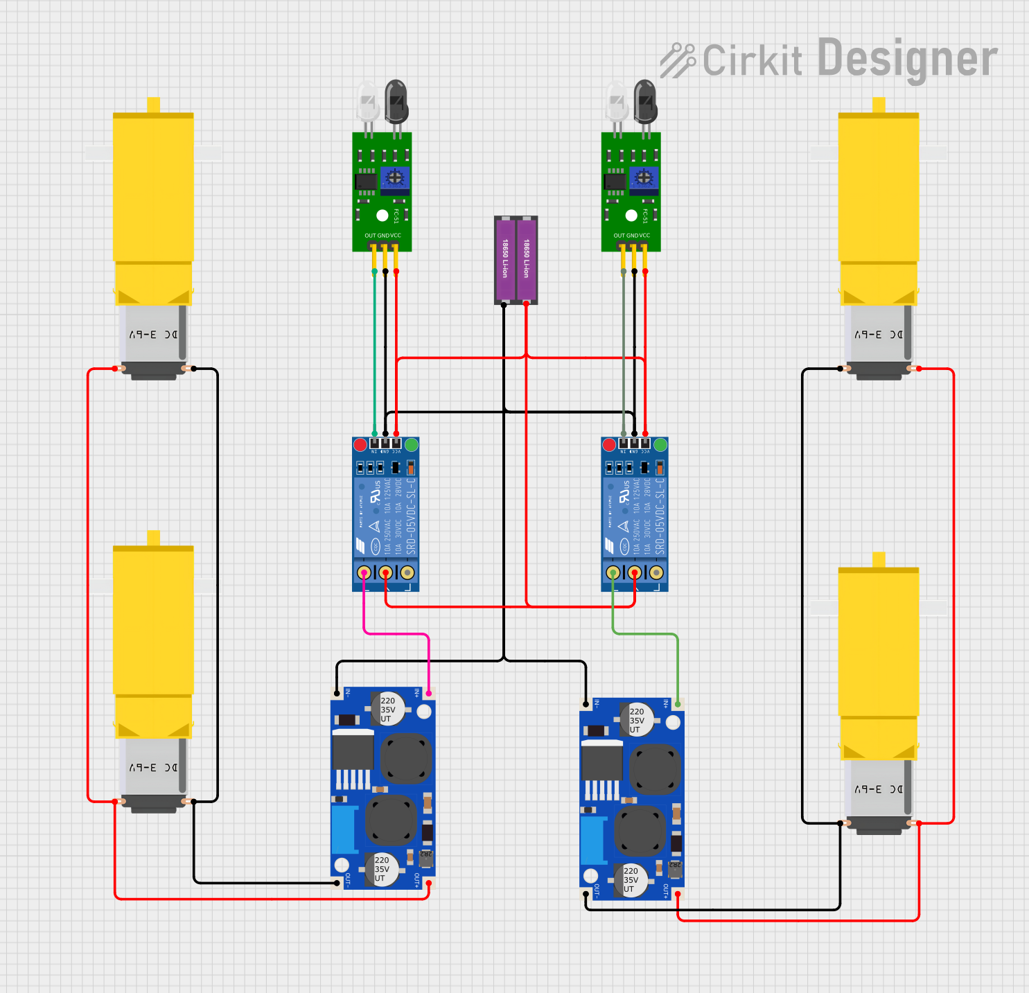
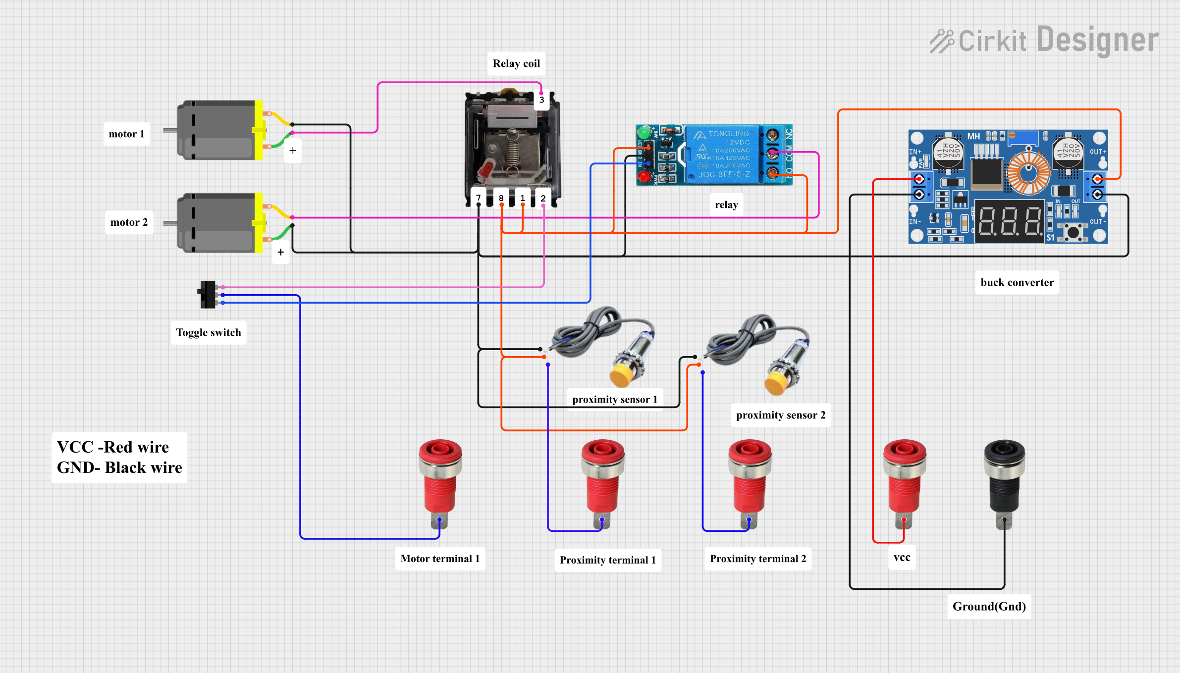
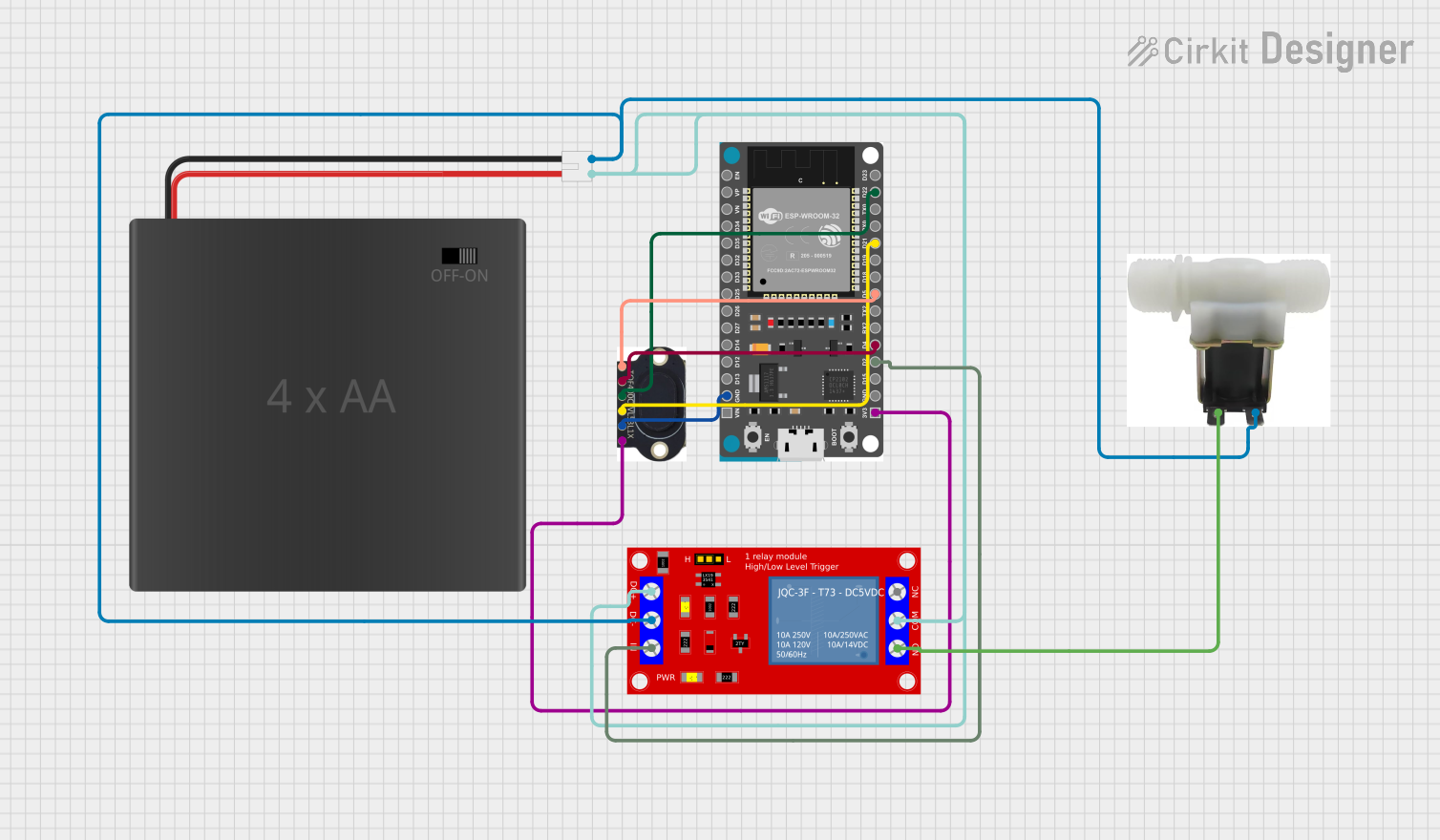
Explore Projects Built with FDX Recloser
Common Applications and Use Cases
- Electrical distribution systems in utility networks
- Industrial power systems requiring fault isolation
- Renewable energy systems for grid protection
- Smart grid applications for automated fault management
Technical Specifications
Key Technical Details
| Parameter | Specification |
|---|---|
| Rated Voltage | 15 kV to 38 kV |
| Rated Current | Up to 800 A |
| Interrupting Capacity | 12.5 kA to 16 kA |
| Operating Mechanism | Magnetic actuator |
| Control Voltage | 24 V DC or 48 V DC |
| Reclosing Operations | Up to 4 programmable reclosing cycles |
| Communication Protocols | DNP3, IEC 61850, Modbus |
| Insulation Medium | Solid dielectric or SF6 gas |
| Operating Temperature Range | -40°C to +55°C |
| Mounting | Pole-mounted or substation-mounted |
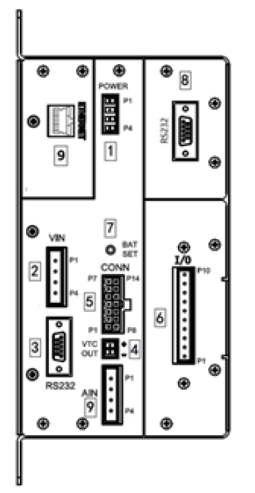
Pin Configuration and Descriptions
The FDX Recloser does not have traditional "pins" like smaller electronic components. Instead, it features terminal connections for power, control, and communication. Below is a description of the key terminals:
| Terminal Name | Description |
|---|---|
| Line Terminal (L1) | Connects to the incoming power line. |
| Load Terminal (L2) | Connects to the outgoing load or distribution line. |
| Control Terminal | Interfaces with the control unit for reclosing logic and fault detection. |
| Ground Terminal | Provides grounding for safety and proper operation. |
| Communication Port | Allows integration with SCADA systems via supported protocols. |
Usage Instructions
How to Use the FDX Recloser in a Circuit
Installation:
- Mount the FDX Recloser on a pole or in a substation as per the manufacturer's guidelines.
- Ensure proper grounding of the recloser to avoid electrical hazards.
- Connect the line and load terminals to the respective power lines.
Control Unit Configuration:
- Connect the control terminal to the recloser control unit.
- Program the reclosing cycles and fault detection parameters using the control unit interface.
Communication Setup:
- Use the communication port to integrate the recloser with a SCADA system.
- Configure the communication protocol (e.g., DNP3, IEC 61850) as required.
Testing:
- Perform a functional test to ensure the recloser operates correctly under fault conditions.
- Verify that the reclosing cycles are executed as programmed.
Important Considerations and Best Practices
- Safety First: Always de-energize the circuit before installation or maintenance.
- Environmental Conditions: Ensure the recloser is suitable for the operating environment (e.g., temperature, humidity).
- Regular Maintenance: Periodically inspect the recloser for wear, corrosion, or damage.
- Firmware Updates: Keep the control unit firmware up to date for optimal performance and security.
Arduino Integration
While the FDX Recloser is not typically controlled by an Arduino, it is possible to use an Arduino to simulate control signals for testing purposes. Below is an example code snippet to send a control signal to the recloser:
// Example Arduino code to send a control signal to the FDX Recloser
const int controlPin = 7; // Pin connected to the recloser's control terminal

void setup() {
  pinMode(controlPin, OUTPUT); // Set the control pin as an output
}

void loop() {
  digitalWrite(controlPin, HIGH); // Send a HIGH signal to close the recloser
  delay(5000); // Wait for 5 seconds
  digitalWrite(controlPin, LOW); // Send a LOW signal to open the recloser
  delay(5000); // Wait for 5 seconds before repeating
}
Note: This code is for simulation purposes only. Ensure compatibility with the recloser's control interface before applying any signals.
Troubleshooting and FAQs
Common Issues and Solutions
| Issue | Possible Cause | Solution |
|---|---|---|
| Recloser does not operate | Control voltage not supplied | Check the control voltage connection. |
| Frequent reclosing cycles | Persistent fault in the circuit | Inspect the circuit for faults or damage. |
| Communication failure with SCADA | Incorrect protocol configuration | Verify and reconfigure the communication. |
| Overheating of the recloser | Excessive load or environmental factors | Reduce the load or improve ventilation. |
FAQs
Can the FDX Recloser handle permanent faults?
- No, the recloser is designed to isolate permanent faults after a set number of reclosing attempts.
What is the lifespan of the FDX Recloser?
- The lifespan depends on operating conditions but typically exceeds 20 years with proper maintenance.
Can the recloser be used in renewable energy systems?
- Yes, it is suitable for protecting renewable energy systems like solar and wind farms.
How do I update the firmware of the control unit?
- Refer to the manufacturer's instructions for firmware updates, typically done via the communication port.
By following this documentation, users can effectively install, configure, and maintain the FDX Recloser for reliable electrical system protection.