How to Use BLDC Motor Controller: Examples, Pinouts, and Specs
Introduction
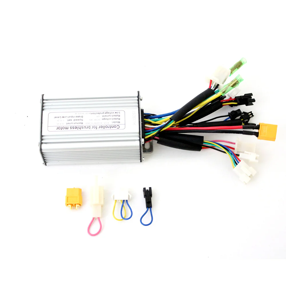
A Brushless DC (BLDC) Motor Controller is an integral component in modern electronic systems requiring precise motor control. Unlike traditional brushed motors, BLDC motors offer higher efficiency, reliability, and lower noise, making them ideal for a wide range of applications including drones, electric vehicles, and industrial automation systems.
The Hallomotor BLDC Motor Controller is designed to provide efficient and precise control over BLDC motors. It uses electronic commutation to drive the motor, eliminating the need for mechanical brushes and thus reducing wear and tear.
Explore Projects Built with BLDC Motor Controller

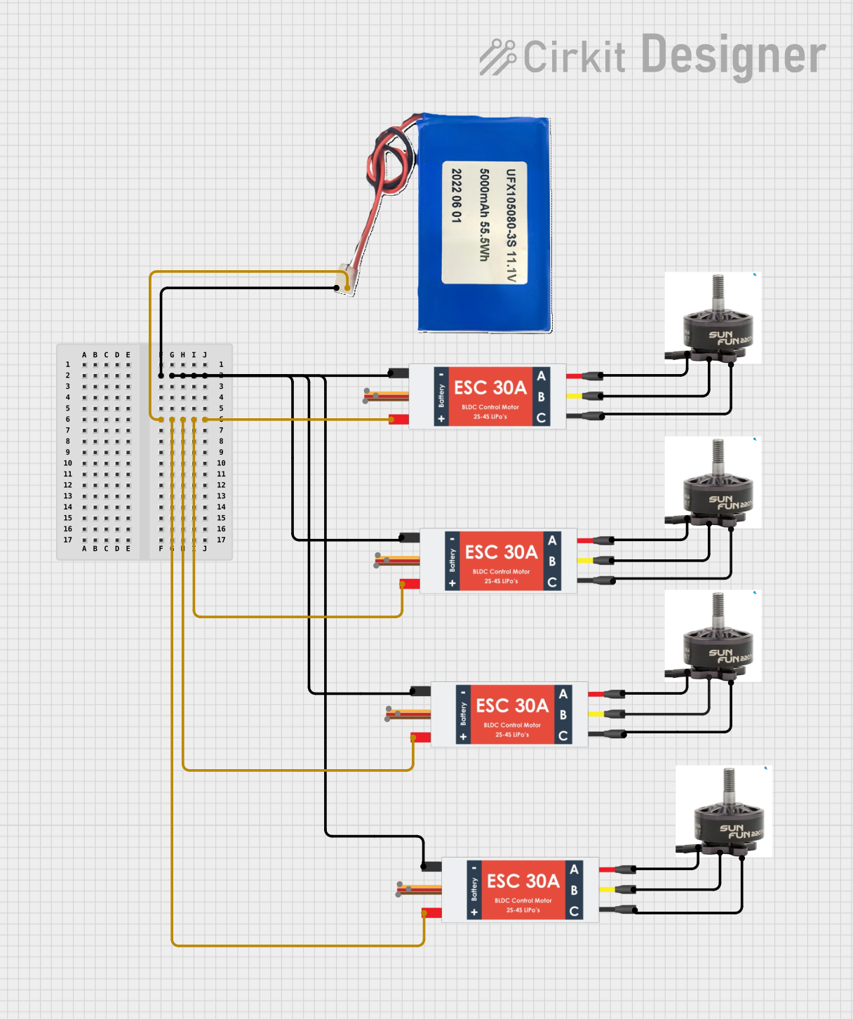
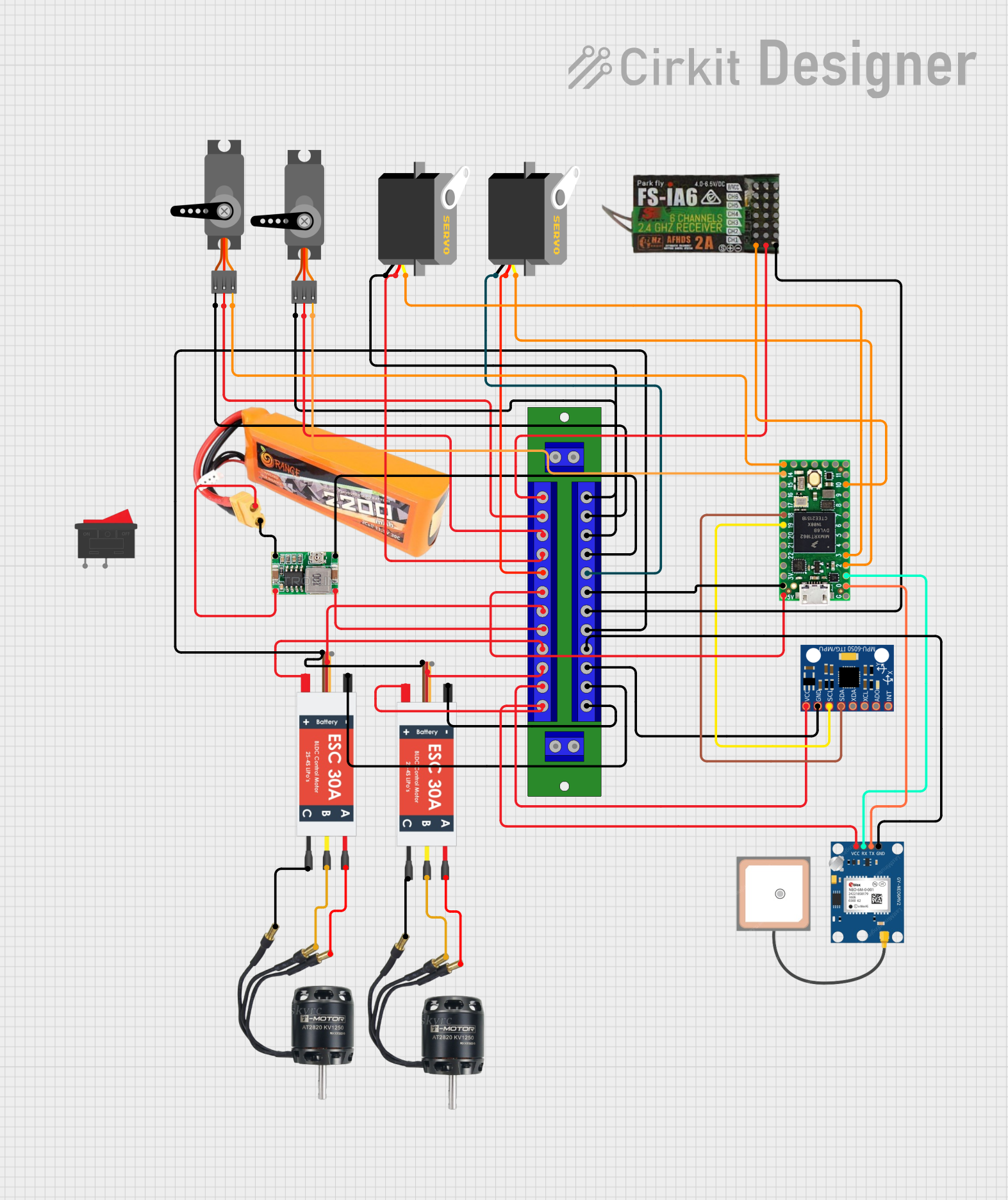
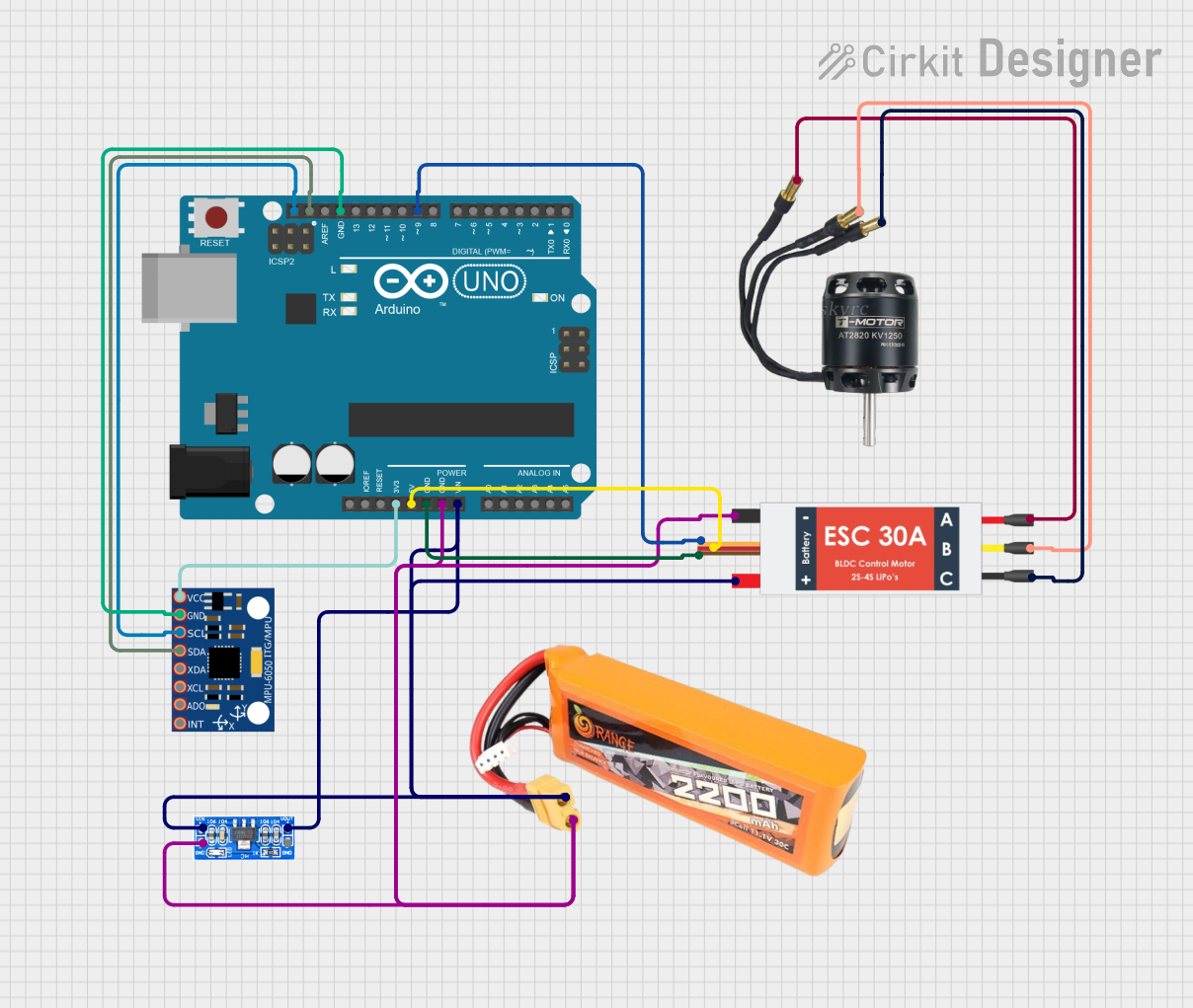
Explore Projects Built with BLDC Motor Controller
Common Applications and Use Cases
- Electric vehicles (e.g., e-bikes, e-scooters)
- Drones and unmanned aerial vehicles (UAVs)
- Industrial automation (e.g., conveyor belts, robotic arms)
- HVAC systems (e.g., fans, blowers)
- Computer peripherals (e.g., cooling fans)
Technical Specifications
Key Technical Details
- Voltage Range: 24V to 72V
- Current Rating: Up to 35A continuous, 50A peak
- Power Rating: Up to 2500W
- Control Method: PWM (Pulse Width Modulation)
- Communication Interface: Optional (CAN, UART, etc.)
Pin Configuration and Descriptions
| Pin Number | Description | Notes |
|---|---|---|
| 1 | Motor Phase A | Connect to BLDC motor phase A |
| 2 | Motor Phase B | Connect to BLDC motor phase B |
| 3 | Motor Phase C | Connect to BLDC motor phase C |
| 4 | Ground | System ground |
| 5 | Power Supply (V+) | 24V to 72V input |
| 6 | Hall Sensor A | Input from motor hall sensor A |
| 7 | Hall Sensor B | Input from motor hall sensor B |
| 8 | Hall Sensor C | Input from motor hall sensor C |
| 9 | Speed Control Signal | PWM signal input |
| 10 | Direction Control | Logic level for direction |
| 11 | Enable | Logic level to enable/disable |
Usage Instructions
How to Use the Component in a Circuit
- Power Connections: Connect the power supply to the controller's V+ and Ground pins, ensuring the voltage is within the specified range.
- Motor Connections: Connect the motor phase wires to the corresponding phase pins on the controller.
- Hall Sensors: Connect the hall sensor outputs from the motor to the hall sensor inputs on the controller.
- Control Signals: Apply a PWM signal to the Speed Control Signal pin to regulate the motor speed. Use the Direction Control pin to change the motor's rotation direction.
- Enable Pin: Use the Enable pin to turn the motor on or off. A high logic level typically enables the motor, while a low level disables it.
Important Considerations and Best Practices
- Ensure that all connections are secure and that the wiring can handle the current requirements.
- Use appropriate heat sinks or cooling methods to manage heat dissipation.
- Implement proper electrical filtering to minimize electromagnetic interference (EMI).
- Always start with a low PWM duty cycle and gradually increase to prevent damage to the motor or controller.
Troubleshooting and FAQs
Common Issues
- Motor not spinning: Check power supply, connections, and ensure the Enable pin is set high.
- Erratic motor behavior: Verify the integrity of hall sensor signals and PWM control signal.
- Overheating: Ensure adequate cooling and that the current does not exceed the controller's rating.
Solutions and Tips for Troubleshooting
- Double-check wiring and connections for any loose or incorrect connections.
- Use an oscilloscope to verify the PWM signal and hall sensor outputs.
- If the controller overheats, reduce the load or improve cooling.
FAQs
Q: Can I use this controller with any BLDC motor? A: The controller is compatible with most BLDC motors within its voltage and current specifications.
Q: How do I reverse the motor direction? A: Change the logic level on the Direction Control pin to reverse the motor's direction.
Q: What PWM frequency should I use? A: The optimal PWM frequency can vary, but it typically ranges from 1 kHz to 20 kHz. Refer to the motor's datasheet for specific recommendations.
Example Code for Arduino UNO
// Define the pins
const int pwmPin = 9; // Speed Control Signal
const int dirPin = 8; // Direction Control
const int enablePin = 7; // Enable

void setup() {
  // Set the pins as outputs
  pinMode(pwmPin, OUTPUT);
  pinMode(dirPin, OUTPUT);
  pinMode(enablePin, OUTPUT);

  // Enable the motor controller
  digitalWrite(enablePin, HIGH);
}

void loop() {
  // Set the motor direction
  digitalWrite(dirPin, HIGH); // Set to LOW to reverse direction

  // Set the motor speed (0 to 255 for PWM)
  analogWrite(pwmPin, 128); // 50% duty cycle for half speed

  // Add your code to change the speed and direction as needed
}
Remember to adjust the PWM values according to your specific motor's requirements and always start with lower values to prevent damage.