
How to Use SI470X: Examples, Pinouts, and Specs
 Design with SI470X in Cirkit Designer
Introduction
The SI470X is a low-power FM radio receiver IC designed for portable applications. It features a built-in digital signal processing (DSP) engine that ensures high-quality audio reception. The chip supports various audio formats and is controlled via an I2C interface, making it highly versatile and easy to integrate into microcontroller-based systems. Its compact design and low power consumption make it ideal for use in portable devices such as MP3 players, smartphones, and handheld radios.
Explore Projects Built with SI470X
 Open Project in Cirkit Designer
 Open Project in Cirkit Designer
 Open Project in Cirkit Designer
 Open Project in Cirkit Designer
Explore Projects Built with SI470X
Open Project in Cirkit DesignerOpen Project in Cirkit DesignerOpen Project in Cirkit DesignerOpen Project in Cirkit DesignerCommon Applications
- Portable FM radios
- MP3 players with FM functionality
- Smartphones with FM radio support
- Embedded systems requiring FM reception
- Automotive infotainment systems
Technical Specifications
Key Technical Details
| Parameter | Value |
|---|---|
| Operating Voltage | 2.7V to 5.5V |
| Operating Current | 19 mA (typical) |
| Frequency Range | 76 MHz to 108 MHz |
| Audio Output | Analog stereo |
| Interface | I2C |
| Sensitivity | -110 dBm |
| Signal-to-Noise Ratio | 60 dB (typical) |
| Package Type | QFN-20 |
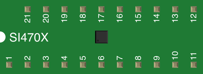
Pin Configuration and Descriptions
| Pin Number | Pin Name | Description |
|---|---|---|
| 1 | GND | Ground |
| 2 | VDD | Power supply input |
| 3 | RFGND | RF ground |
| 4 | LOUT | Left audio output |
| 5 | ROUT | Right audio output |
| 6 | SCLK | I2C clock input |
| 7 | SDIO | I2C data input/output |
| 8 | RST | Reset pin (active low) |
| 9 | ANTENNA | FM antenna input |
| 10 | GPIO1 | General-purpose I/O pin 1 |
| 11 | GPIO2 | General-purpose I/O pin 2 |
| 12-20 | NC | Not connected |
Usage Instructions
How to Use the SI470X in a Circuit
- Power Supply: Connect the VDD pin to a stable power source (2.7V to 5.5V) and the GND pin to ground.
- Antenna: Attach an FM antenna to the ANTENNA pin for signal reception.
- Audio Output: Connect the LOUT and ROUT pins to an audio amplifier or headphones for stereo output.
- I2C Communication: Use the SCLK and SDIO pins to interface with a microcontroller via the I2C protocol.
- Reset: Pull the RST pin low momentarily to reset the chip during initialization.
Important Considerations
- Use decoupling capacitors near the VDD pin to ensure stable operation.
- Keep the antenna trace as short as possible to minimize signal loss.
- Avoid placing the chip near high-frequency noise sources to maintain signal integrity.
- Ensure proper pull-up resistors are used on the I2C lines (SCLK and SDIO).
Example: Connecting the SI470X to an Arduino UNO
Below is an example of how to interface the SI470X with an Arduino UNO to receive FM radio signals.
Circuit Connections
| SI470X Pin | Arduino UNO Pin |
|---|---|
| VDD | 3.3V |
| GND | GND |
| SCLK | A5 (SCL) |
| SDIO | A4 (SDA) |
| RST | Digital Pin 2 |
| LOUT/ROUT | Audio Amplifier |
Arduino Code Example
#include <Wire.h>
#include <SI470X.h> // Include the SI470X library

SI470X radio; // Create an instance of the SI470X class

void setup() {
  Wire.begin(); // Initialize I2C communication
  Serial.begin(9600); // Initialize serial communication for debugging

  pinMode(2, OUTPUT); // Set the reset pin as output
  digitalWrite(2, LOW); // Hold the SI470X in reset
  delay(100); // Wait for 100ms
  digitalWrite(2, HIGH); // Release the reset pin

  if (!radio.begin()) {
    Serial.println("Failed to initialize SI470X!");
    while (1); // Halt if initialization fails
  }

  radio.setFrequency(101.1); // Set the FM frequency to 101.1 MHz
  Serial.println("Radio initialized and tuned to 101.1 MHz");
}

void loop() {
  // Continuously monitor signal strength
  int signalStrength = radio.getSignalStrength();
  Serial.print("Signal Strength: ");
  Serial.println(signalStrength);

  delay(1000); // Wait for 1 second before updating
}
Notes
- Install the
SI470Xlibrary in the Arduino IDE before uploading the code. - Adjust the frequency in the
setFrequency()function to tune to your desired FM station.
Troubleshooting and FAQs
Common Issues
No Audio Output
- Ensure the antenna is properly connected to the ANTENNA pin.
- Verify that the audio output pins (LOUT and ROUT) are connected to an amplifier or headphones.
I2C Communication Failure
- Check the pull-up resistors on the SCLK and SDIO lines.
- Ensure the I2C address of the SI470X matches the address used in the code.
Poor Signal Reception
- Use a longer or higher-quality antenna.
- Avoid placing the SI470X near sources of electromagnetic interference.
Chip Not Initializing
- Verify the RST pin is correctly toggled during startup.
- Check the power supply voltage and ensure it is within the specified range.
FAQs
Q: Can the SI470X receive AM radio signals?
A: No, the SI470X is designed specifically for FM radio reception.
Q: What is the maximum distance for FM signal reception?
A: The reception range depends on the strength of the FM transmitter and the quality of the antenna. Typically, it can range from a few kilometers to tens of kilometers.
Q: Can I use the SI470X with a 5V microcontroller?
A: Yes, but ensure proper level shifting for the I2C lines if the microcontroller operates at 5V logic levels.
Q: Is an external crystal oscillator required?
A: No, the SI470X has an internal oscillator, but an external reference clock can be used for improved performance if needed.