How to Use Thermostat: Examples, Pinouts, and Specs
Introduction
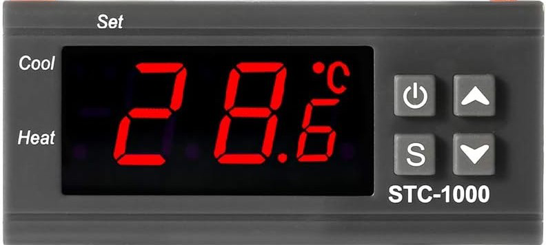
The STC-1000 is a versatile, generic thermostat designed to regulate temperature by controlling heating and cooling systems. It is widely used in applications requiring precise temperature management, such as aquariums, fermentation chambers, greenhouses, and HVAC systems. This device allows users to set a desired temperature range, automatically switching between heating and cooling modes to maintain the setpoint.
Explore Projects Built with Thermostat
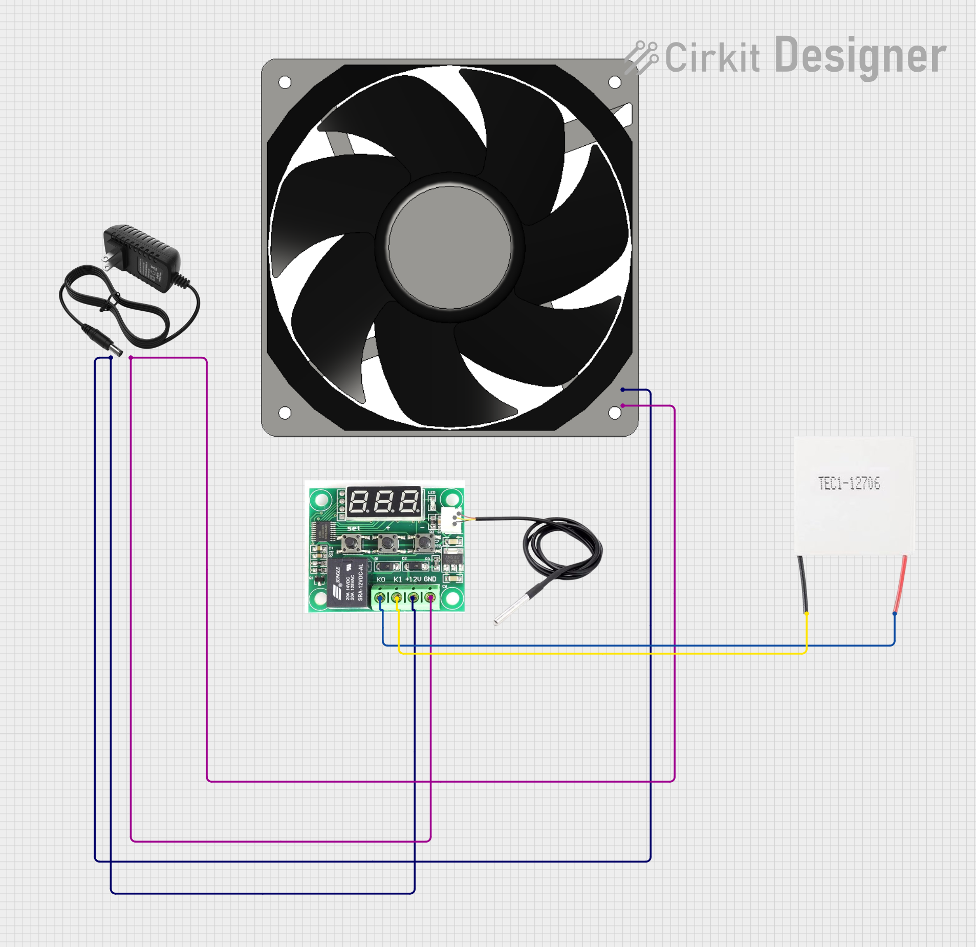
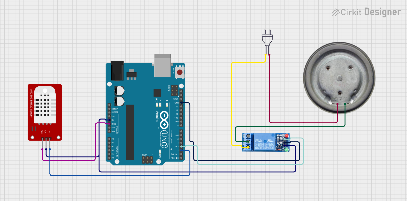
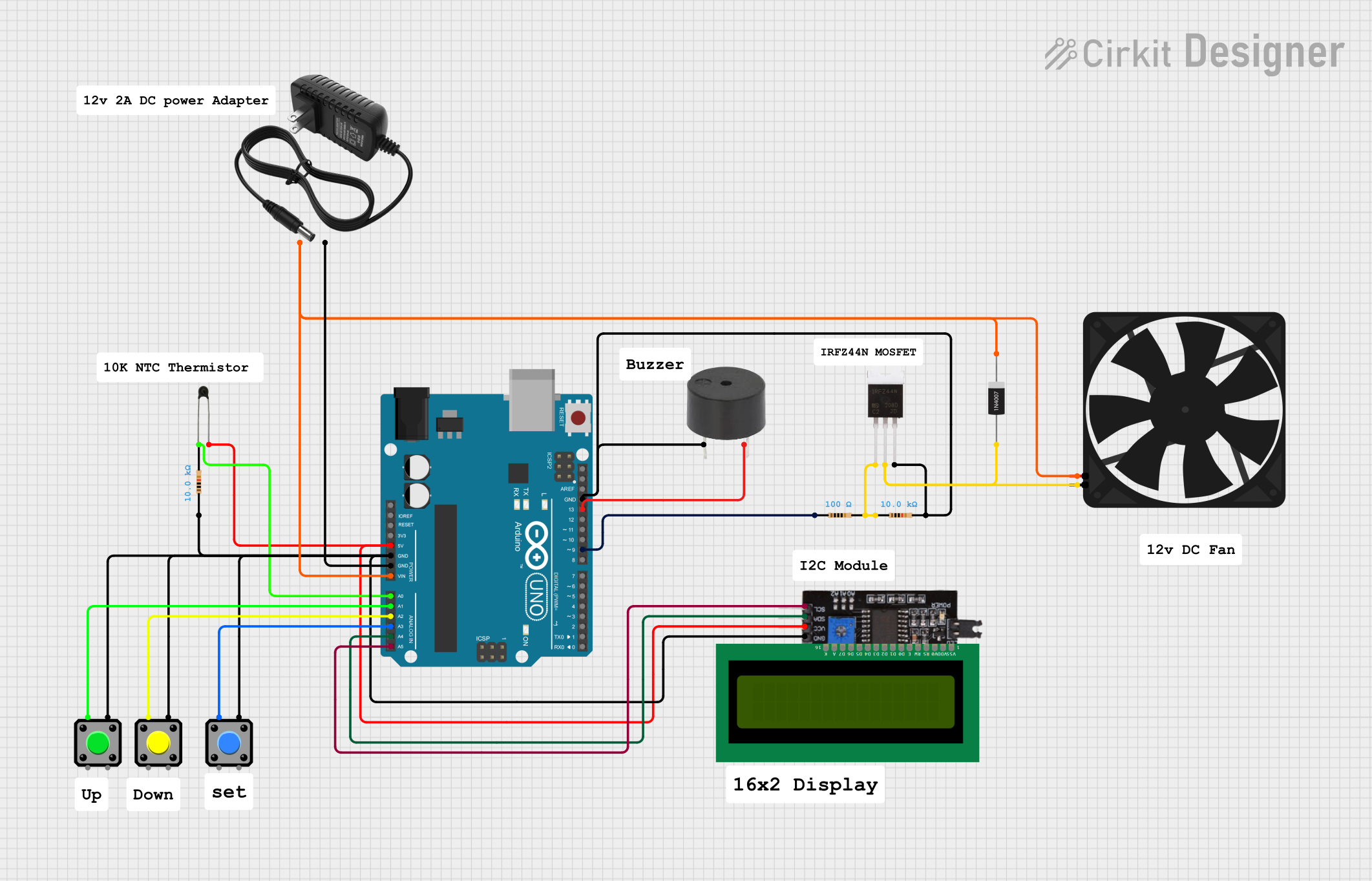
Explore Projects Built with Thermostat
Common Applications
- Temperature control in homebrewing and fermentation processes
- Aquarium temperature regulation
- Greenhouse climate management
- HVAC systems for residential or commercial use
- Food storage and refrigeration systems
Technical Specifications
Key Technical Details
| Parameter | Value |
|---|---|
| Manufacturer | Generic |
| Part ID | STC-1000 |
| Input Voltage | AC 110V-220V ±10% |
| Temperature Range | -50°C to 99°C (-58°F to 210°F) |
| Temperature Accuracy | ±1°C |
| Sensor Type | NTC (10kΩ) sensor |
| Relay Output Capacity | Heating: 10A/220V AC |
| Cooling: 10A/220V AC | |
| Power Consumption | <3W |
| Display Type | LED digital display |
| Operating Temperature | -10°C to 60°C |
| Storage Temperature | -20°C to 75°C |
Pin Configuration and Descriptions
The STC-1000 has a total of 6 terminals for wiring. Below is the pin configuration:
| Terminal Number | Description |
|---|---|
| 1 | Power Input (Live/Hot) |
| 2 | Power Input (Neutral) |
| 3 | Cooling Output (Live/Hot) |
| 4 | Heating Output (Live/Hot) |
| 5 | Sensor Input (NTC Sensor - Positive) |
| 6 | Sensor Input (NTC Sensor - Negative) |
Usage Instructions
How to Use the STC-1000 in a Circuit
Wiring the Device:
- Connect terminals 1 and 2 to the AC power supply (110V-220V).
- Connect the cooling device (e.g., a fan or compressor) to terminal 3.
- Connect the heating device (e.g., a heater or heating pad) to terminal 4.
- Attach the NTC temperature sensor to terminals 5 and 6.
Setting the Temperature:
- Power on the device. The LED display will show the current temperature.
- Press and hold the "SET" button to enter the temperature setting mode.
- Use the arrow buttons to adjust the desired temperature setpoint.
- Press "SET" again to save the settings.
Configuring Parameters:
- Press and hold the "SET" button for 3 seconds to enter the parameter configuration menu.
- Use the arrow buttons to navigate through parameters such as hysteresis, temperature calibration, and delay protection.
- Adjust the values as needed and press "SET" to confirm.
Important Considerations and Best Practices
- Ensure the power supply voltage matches the device's input voltage range (110V-220V).
- Place the NTC sensor in a location that accurately reflects the temperature of the controlled environment.
- Avoid exposing the device to moisture or extreme temperatures beyond its operating range.
- Use appropriate fuses or circuit breakers to protect the thermostat and connected devices.
- Regularly inspect the sensor and wiring for wear or damage.
Example: Connecting to an Arduino UNO
While the STC-1000 is a standalone device, it can be integrated with an Arduino UNO for advanced monitoring or control. Below is an example code snippet to read the temperature from the NTC sensor:
// Example code to read temperature from an NTC sensor connected to Arduino
// Note: This assumes the NTC sensor is connected to an analog pin (e.g., A0).

const int sensorPin = A0; // Analog pin connected to the NTC sensor
const float referenceResistance = 10000.0; // 10kΩ reference resistor
const float nominalResistance = 10000.0;  // 10kΩ at 25°C
const float nominalTemperature = 25.0;    // Nominal temperature in °C
const float betaCoefficient = 3950.0;     // Beta coefficient of the NTC sensor
const float seriesResistor = 10000.0;     // Series resistor value in ohms

void setup() {
  Serial.begin(9600); // Initialize serial communication
}

void loop() {
  int analogValue = analogRead(sensorPin); // Read analog value from sensor
  float voltage = analogValue * (5.0 / 1023.0); // Convert to voltage
  float resistance = (seriesResistor * (5.0 - voltage)) / voltage; // Calculate resistance

  // Calculate temperature using the Steinhart-Hart equation
  float steinhart;
  steinhart = resistance / nominalResistance; // (R/Ro)
  steinhart = log(steinhart);                 // ln(R/Ro)
  steinhart /= betaCoefficient;               // 1/B * ln(R/Ro)
  steinhart += 1.0 / (nominalTemperature + 273.15); // + (1/To)
  steinhart = 1.0 / steinhart;                // Invert
  steinhart -= 273.15;                        // Convert to °C

  Serial.print("Temperature: ");
  Serial.print(steinhart);
  Serial.println(" °C");

  delay(1000); // Wait 1 second before the next reading
}
Troubleshooting and FAQs
Common Issues and Solutions
Device Does Not Power On:
- Check the power supply voltage and ensure proper wiring to terminals 1 and 2.
- Inspect the fuse (if applicable) and replace it if blown.
Incorrect Temperature Reading:
- Verify the NTC sensor is properly connected to terminals 5 and 6.
- Ensure the sensor is placed in an appropriate location for accurate measurement.
- Use the temperature calibration parameter to adjust for any discrepancies.
Heating or Cooling Device Does Not Activate:
- Confirm the devices are correctly wired to terminals 3 and 4.
- Check the relay output capacity and ensure the connected devices do not exceed the rated current (10A).
Display Shows Error Codes:
- E1: Sensor is disconnected or damaged. Check the sensor wiring and replace if necessary.
- EE: Internal memory error. Reset the device or contact the manufacturer.
- HH/LL: Temperature exceeds the measurable range. Verify the sensor placement and environment.
Tips for Troubleshooting
- Always disconnect the power supply before inspecting or modifying the wiring.
- Use a multimeter to check continuity and voltage levels during troubleshooting.
- Refer to the user manual for additional error codes and advanced settings.
By following this documentation, users can effectively utilize the STC-1000 thermostat for a wide range of temperature control applications.