Cirkit Designer Logo
Cirkit Designer
Your all-in-one circuit design IDE
Home / 
Component Documentation

How to Use CAN bus transceiver: Examples, Pinouts, and Specs

Image of CAN bus transceiver
Cirkit Designer LogoDesign with CAN bus transceiver in Cirkit Designer

Introduction

The SN65HVD230 is a high-performance CAN bus transceiver manufactured by Waveshare. It is designed to enable communication between microcontrollers and devices on a Controller Area Network (CAN). This transceiver converts the digital signals from a microcontroller into differential signals suitable for the CAN bus and vice versa, ensuring robust and reliable data transmission.

Explore Projects Built with CAN bus transceiver

Use Cirkit Designer to design, explore, and prototype these projects online. Some projects support real-time simulation. Click "Open Project" to start designing instantly!
Dual Raspberry Pi 2B CAN BUS Communication Interface with Pushbutton Interaction
Image of BSP4: A project utilizing CAN bus transceiver in a practical application
This circuit features two Raspberry Pi 2B microcontrollers connected to separate CAN BUS modules, forming a CAN network for data exchange. A pushbutton is included for user interaction, interfaced with GPIO pins on both Raspberry Pis.
Cirkit Designer LogoOpen Project in Cirkit Designer
Arduino UNO WiFi CAN Bus Interface with Sensor/Actuator Module
Image of CAN : SN65HVD230 via NS-LS2(LevelConverter)2: A project utilizing CAN bus transceiver in a practical application
This circuit features two Arduino UNO R4 WiFi microcontrollers interfaced with NS-LS2 light sensors and CAN_SN65HVD230 CAN bus transceivers. The Arduinos are configured to read light intensity data from the NS-LS2 sensors and communicate with each other over a CAN network, likely for a distributed sensing application. Power distribution is managed with 3.3V and 5V connections to the respective components, and the ground connections are shared across the devices to complete the circuit.
Cirkit Designer LogoOpen Project in Cirkit Designer
STM32 and Arduino UNO Based Dual RS485 Communication Interface
Image of STM to Arduino RS485: A project utilizing CAN bus transceiver in a practical application
This circuit consists of two microcontrollers, an STM32F103C8T6 and an Arduino UNO, each interfaced with separate RS485 transceiver modules for serial communication. The STM32F103C8T6 controls the RE (Receiver Enable) and DE (Driver Enable) pins of one RS485 module to manage its operation, and communicates via the A9 and A10 pins for DI (Data Input) and RO (Receiver Output), respectively. The Arduino UNO is similarly connected to another RS485 module, with digital pins D2 and D3 interfacing with DI and RO, and D8 controlling both RE and DE. The RS485 modules are connected to each other through their A and B differential communication lines, enabling serial data exchange between the two microcontrollers over a robust and long-distance capable RS485 network.
Cirkit Designer LogoOpen Project in Cirkit Designer
Arduino Nano OBD-II Data Logger with TFT Display and CAN Bus Interface
Image of inzynierka: A project utilizing CAN bus transceiver in a practical application
This circuit is an OBD-II vehicle diagnostic interface that uses an Arduino Nano to communicate with a vehicle's CAN bus via an MCP2515 CAN controller. It includes a 7805 voltage regulator to step down the vehicle's 12V supply to 5V, powering the Arduino and other components, and a 1.44-inch TFT display for visual output. A pushbutton is also included for user interaction.
Cirkit Designer LogoOpen Project in Cirkit Designer

Explore Projects Built with CAN bus transceiver

Use Cirkit Designer to design, explore, and prototype these projects online. Some projects support real-time simulation. Click "Open Project" to start designing instantly!
Image of BSP4: A project utilizing CAN bus transceiver in a practical application
Dual Raspberry Pi 2B CAN BUS Communication Interface with Pushbutton Interaction
This circuit features two Raspberry Pi 2B microcontrollers connected to separate CAN BUS modules, forming a CAN network for data exchange. A pushbutton is included for user interaction, interfaced with GPIO pins on both Raspberry Pis.
Cirkit Designer LogoOpen Project in Cirkit Designer
Image of CAN : SN65HVD230 via NS-LS2(LevelConverter)2: A project utilizing CAN bus transceiver in a practical application
Arduino UNO WiFi CAN Bus Interface with Sensor/Actuator Module
This circuit features two Arduino UNO R4 WiFi microcontrollers interfaced with NS-LS2 light sensors and CAN_SN65HVD230 CAN bus transceivers. The Arduinos are configured to read light intensity data from the NS-LS2 sensors and communicate with each other over a CAN network, likely for a distributed sensing application. Power distribution is managed with 3.3V and 5V connections to the respective components, and the ground connections are shared across the devices to complete the circuit.
Cirkit Designer LogoOpen Project in Cirkit Designer
Image of STM to Arduino RS485: A project utilizing CAN bus transceiver in a practical application
STM32 and Arduino UNO Based Dual RS485 Communication Interface
This circuit consists of two microcontrollers, an STM32F103C8T6 and an Arduino UNO, each interfaced with separate RS485 transceiver modules for serial communication. The STM32F103C8T6 controls the RE (Receiver Enable) and DE (Driver Enable) pins of one RS485 module to manage its operation, and communicates via the A9 and A10 pins for DI (Data Input) and RO (Receiver Output), respectively. The Arduino UNO is similarly connected to another RS485 module, with digital pins D2 and D3 interfacing with DI and RO, and D8 controlling both RE and DE. The RS485 modules are connected to each other through their A and B differential communication lines, enabling serial data exchange between the two microcontrollers over a robust and long-distance capable RS485 network.
Cirkit Designer LogoOpen Project in Cirkit Designer
Image of inzynierka: A project utilizing CAN bus transceiver in a practical application
Arduino Nano OBD-II Data Logger with TFT Display and CAN Bus Interface
This circuit is an OBD-II vehicle diagnostic interface that uses an Arduino Nano to communicate with a vehicle's CAN bus via an MCP2515 CAN controller. It includes a 7805 voltage regulator to step down the vehicle's 12V supply to 5V, powering the Arduino and other components, and a 1.44-inch TFT display for visual output. A pushbutton is also included for user interaction.
Cirkit Designer LogoOpen Project in Cirkit Designer

Common Applications and Use Cases

  • Automotive systems (e.g., engine control units, infotainment systems)
  • Industrial automation and control
  • Medical equipment
  • Robotics and drones
  • IoT devices requiring CAN communication

Technical Specifications

The SN65HVD230 is a robust and versatile transceiver with the following key specifications:

Parameter Value
Supply Voltage (Vcc) 3.3V
Bus Voltage Range -7V to +12V
Data Rate Up to 1 Mbps
Operating Temperature -40°C to +85°C
Standby Current < 370 µA
Differential Output Voltage 1.5V to 3V
ESD Protection ±16 kV (Human Body Model)

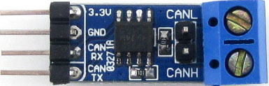
Pin Configuration and Descriptions

The SN65HVD230 transceiver is typically available in an 8-pin SOIC package. Below is the pinout and description:

Pin Number Pin Name Description
1 CANH High-level CAN bus line
2 CANL Low-level CAN bus line
3 RS Mode selection pin (controls normal, standby, or silent mode)
4 GND Ground
5 Vcc Power supply (3.3V)
6 D (RXD) Receive data output (connected to microcontroller RX pin)
7 R (TXD) Transmit data input (connected to microcontroller TX pin)
8 NC No connection (not used)

Usage Instructions

How to Use the SN65HVD230 in a Circuit

  1. Power Supply: Connect the Vcc pin to a 3.3V power source and the GND pin to ground.
  2. CAN Bus Lines: Connect the CANH and CANL pins to the corresponding lines on the CAN bus.
  3. Microcontroller Interface:
    • Connect the TXD pin of the transceiver to the TX pin of the microcontroller.
    • Connect the RXD pin of the transceiver to the RX pin of the microcontroller.
  4. Mode Selection:
    • Use the RS pin to configure the operating mode:
      • Connect RS to GND for normal mode.
      • Connect RS to Vcc for standby mode.
      • Use a resistor to set a specific slope control for silent mode.
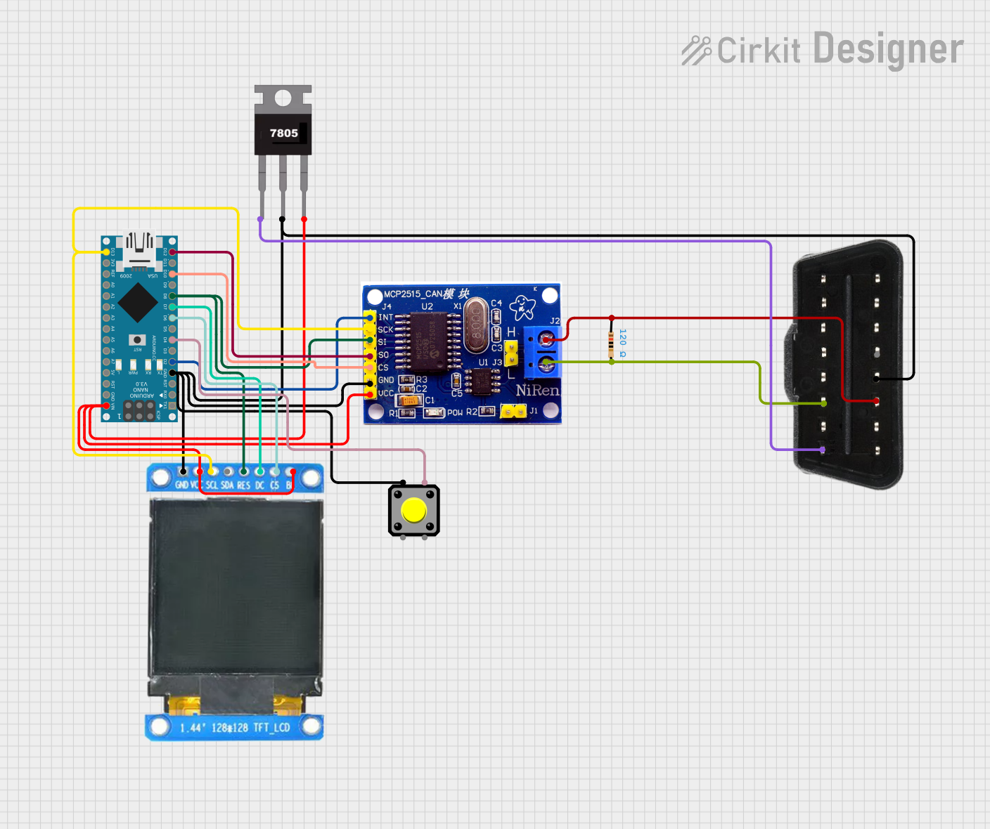
  5. Termination Resistor: Add a 120-ohm termination resistor between CANH and CANL if the transceiver is at the end of the CAN bus.

Important Considerations and Best Practices

  • Ensure the supply voltage is stable and within the specified range (3.3V).
  • Use proper grounding to minimize noise and ensure reliable communication.
  • Place the transceiver close to the microcontroller to reduce signal degradation.
  • If using multiple transceivers on the same CAN bus, ensure only the devices at the ends of the bus have termination resistors.

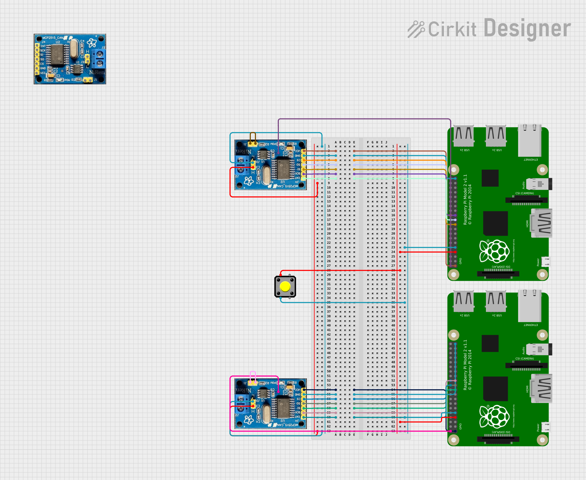
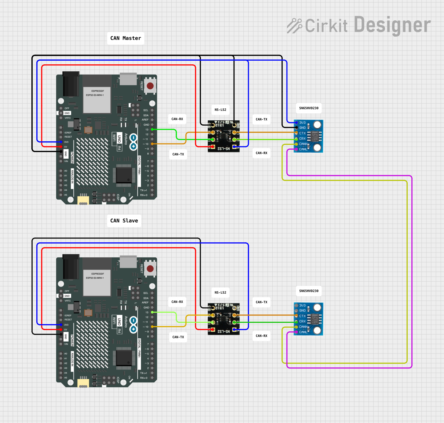
Example Code for Arduino UNO

Below is an example of how to use the SN65HVD230 with an Arduino UNO for basic CAN communication. This example assumes the use of an external CAN controller (e.g., MCP2515) since the Arduino UNO does not have a built-in CAN controller.

#include <SPI.h>
#include <mcp_can.h>

// Define the SPI CS pin for the MCP2515 CAN controller
#define CAN_CS_PIN 10

// Initialize the MCP_CAN object
MCP_CAN CAN(CAN_CS_PIN);

void setup() {
  Serial.begin(115200); // Initialize serial communication for debugging
  while (!Serial);

  // Initialize the CAN controller at 500 kbps
  if (CAN.begin(MCP_ANY, CAN_500KBPS, MCP_8MHZ) == CAN_OK) {
    Serial.println("CAN bus initialized successfully!");
  } else {
    Serial.println("Error initializing CAN bus.");
    while (1);
  }

  // Set the CAN controller to normal mode
  CAN.setMode(MCP_NORMAL);
  Serial.println("CAN bus set to normal mode.");
}

void loop() {
  // Example: Send a CAN message
  byte data[8] = {0x01, 0x02, 0x03, 0x04, 0x05, 0x06, 0x07, 0x08};
  if (CAN.sendMsgBuf(0x100, 0, 8, data) == CAN_OK) {
    Serial.println("Message sent successfully!");
  } else {
    Serial.println("Error sending message.");
  }

  delay(1000); // Wait 1 second before sending the next message
}

Troubleshooting and FAQs

Common Issues and Solutions

  1. No Communication on the CAN Bus:

    • Verify the wiring between the transceiver, microcontroller, and CAN bus.
    • Ensure the RS pin is configured correctly for the desired mode.
    • Check that the termination resistors are properly placed at the ends of the CAN bus.
  2. High Noise or Data Errors:

    • Use shielded cables for the CAN bus lines to reduce electromagnetic interference.
    • Ensure proper grounding of all devices on the CAN bus.
  3. Transceiver Overheating:

    • Check for short circuits on the CANH and CANL lines.
    • Ensure the supply voltage does not exceed 3.3V.
  4. Microcontroller Not Receiving Data:

    • Verify the connections between the RXD/TXD pins and the microcontroller.
    • Check the baud rate configuration of the CAN controller and ensure it matches the network.

FAQs

Q: Can the SN65HVD230 operate at 5V?
A: No, the SN65HVD230 is designed to operate at 3.3V. Using 5V may damage the component.

Q: How do I calculate the resistor value for slope control?
A: The resistor value on the RS pin determines the slope of the CAN signals. Refer to the SN65HVD230 datasheet for detailed calculations based on your application.

Q: Can I use the SN65HVD230 for long-distance communication?
A: Yes, the SN65HVD230 supports long-distance communication, but ensure proper termination and use of shielded cables to minimize signal degradation.