How to Use Solar Power Manager V5: Examples, Pinouts, and Specs
Introduction
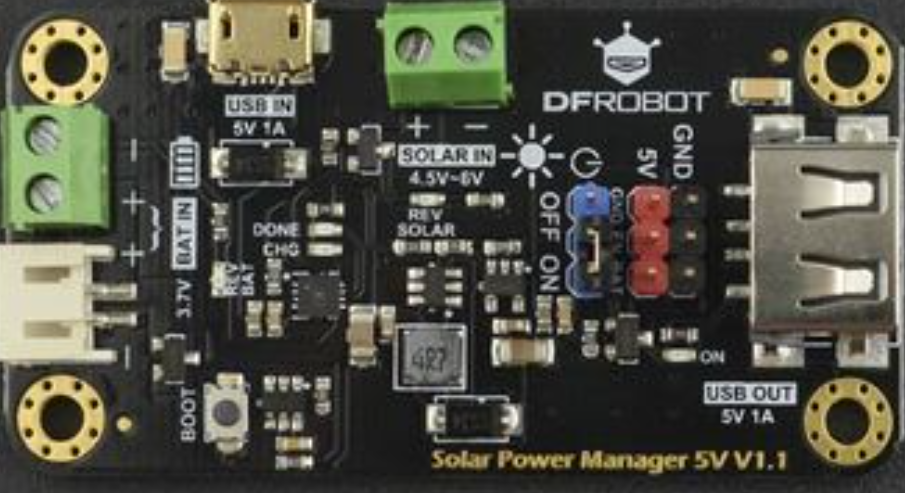
The Solar Power Manager V5 (SKU: DFR0559) by DFRobot is a versatile power management module designed to efficiently harvest and manage solar energy for various electronic projects. It includes features such as Maximum Power Point Tracking (MPPT), battery charging, and multiple output options, making it an ideal choice for solar-powered applications.
Explore Projects Built with Solar Power Manager V5
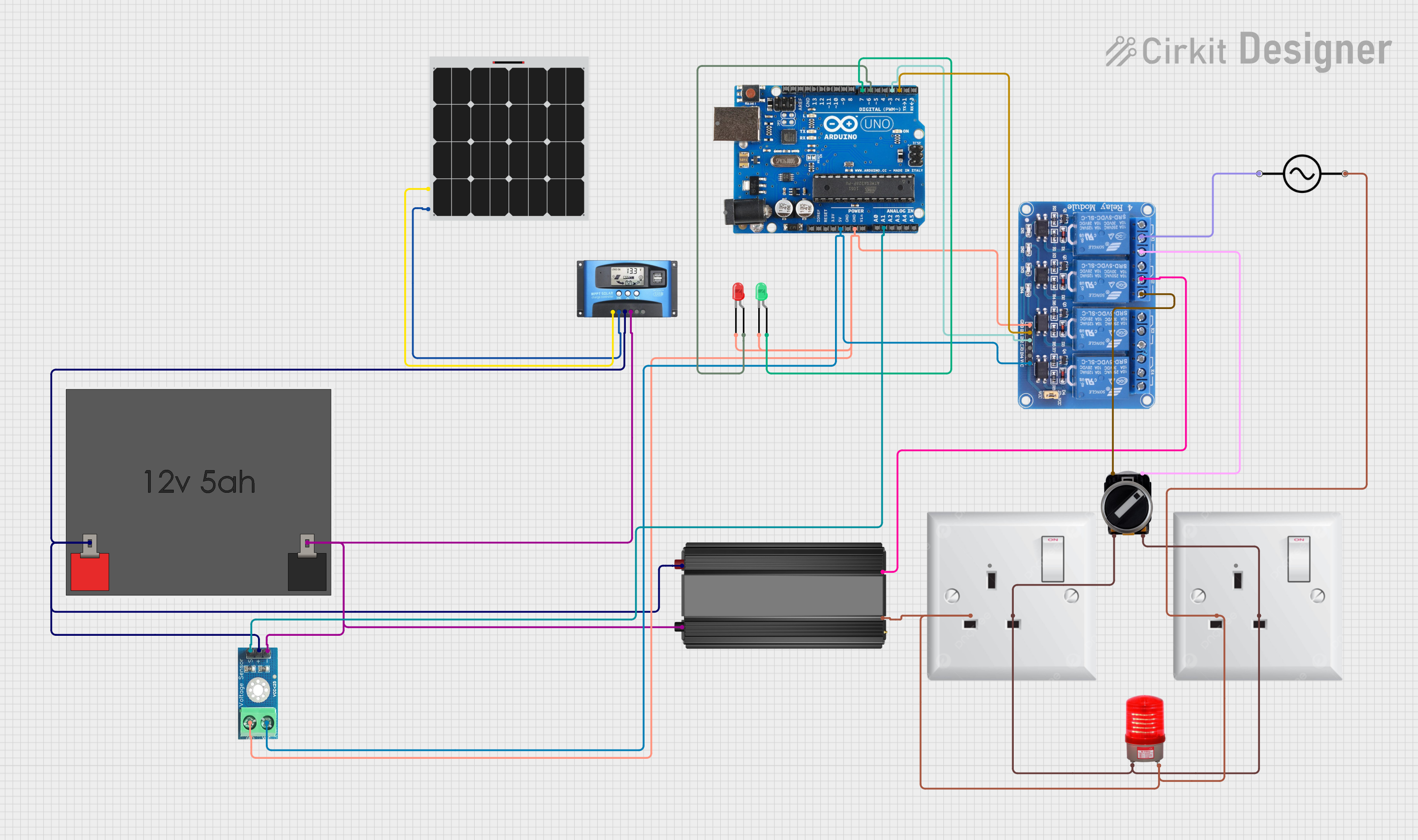
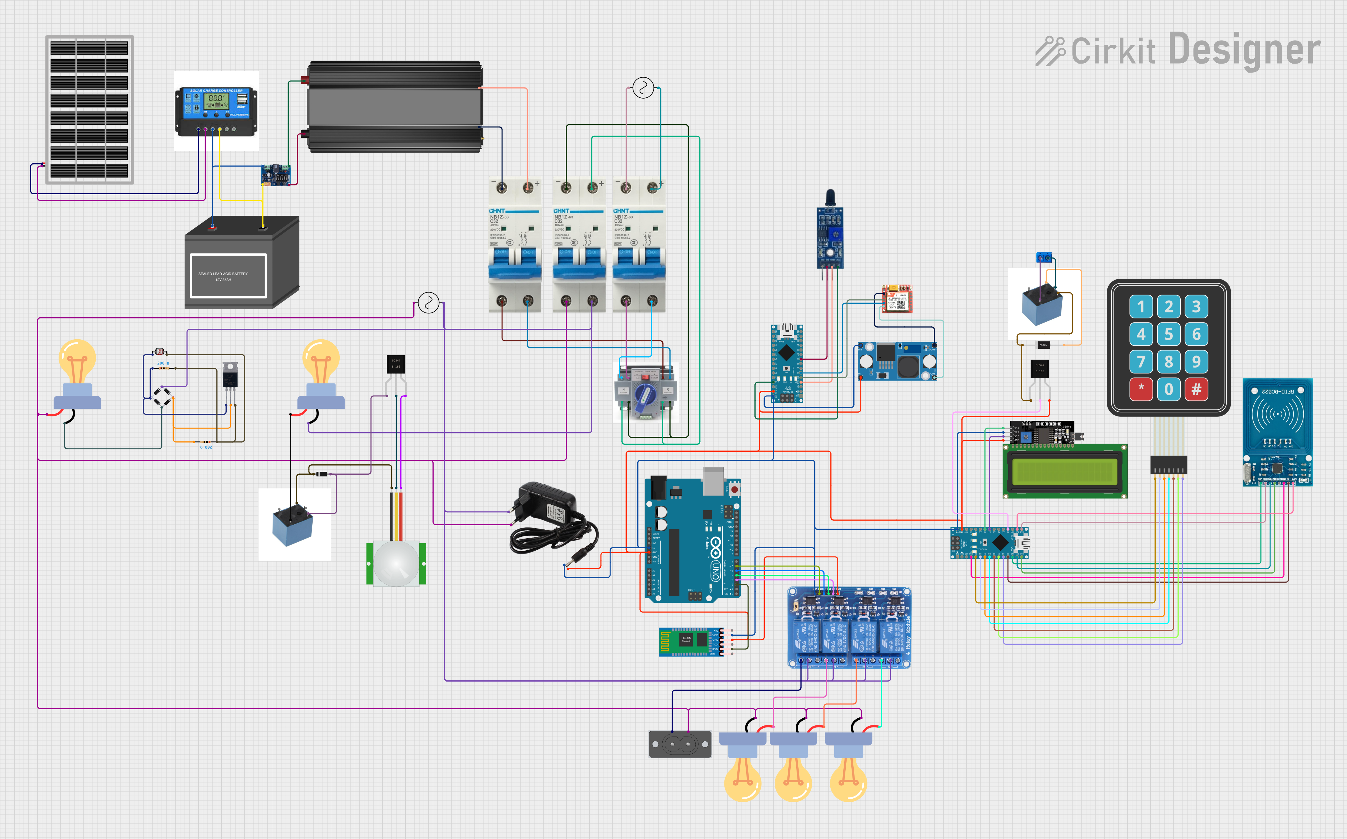
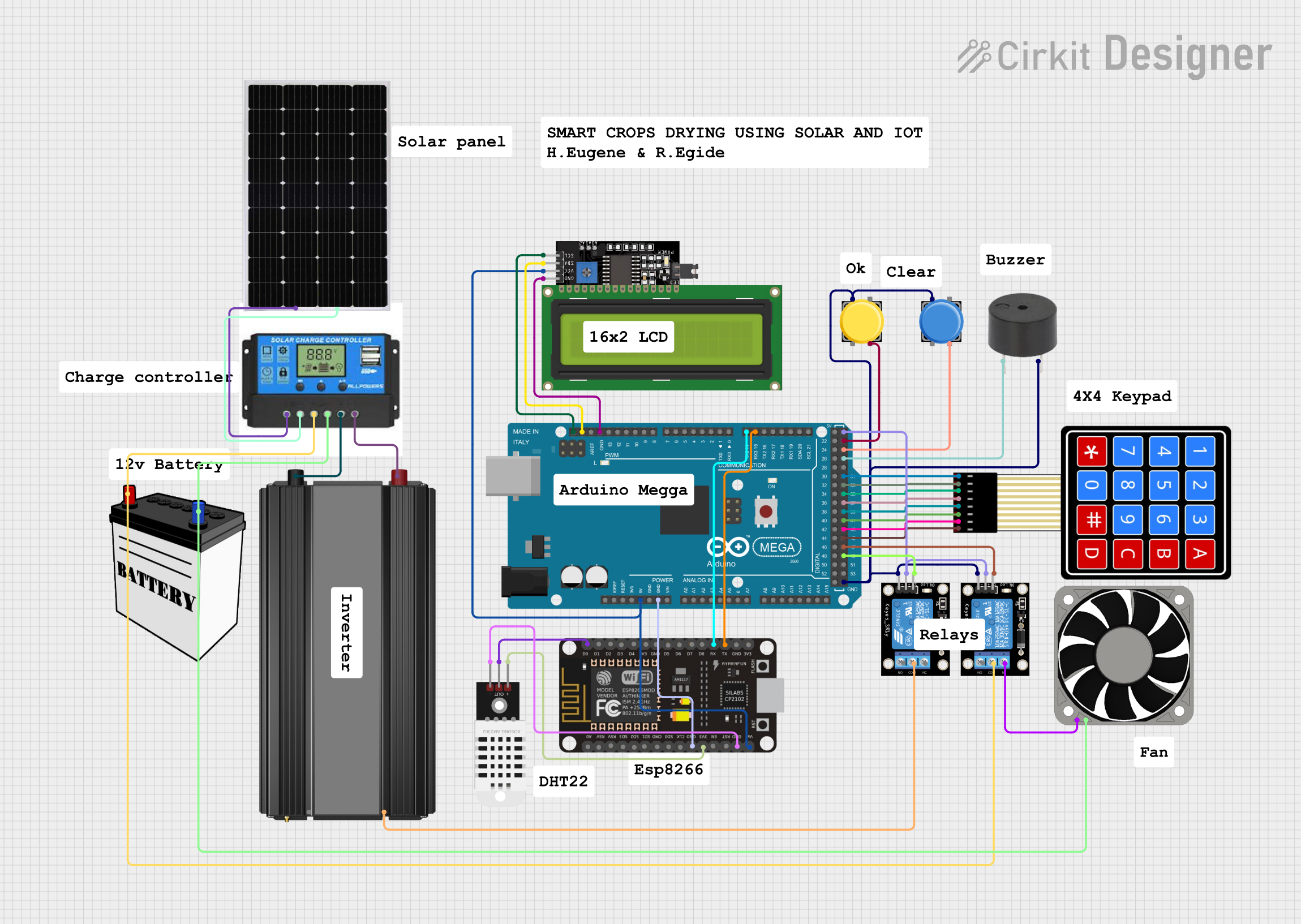
Explore Projects Built with Solar Power Manager V5
Common Applications and Use Cases
- Solar-powered IoT devices
- Remote environmental monitoring systems
- Portable solar chargers
- Solar-powered robotics
- Off-grid renewable energy projects
Technical Specifications
Key Technical Details
| Parameter | Value |
|---|---|
| Input Voltage Range | 4.4V - 6V |
| Output Voltage | 3.3V, 5V |
| Output Current | 1A (max) |
| Battery Charging Current | 500mA (default), adjustable via resistor |
| MPPT Efficiency | Up to 95% |
| Operating Temperature | -40°C to 85°C |
| Dimensions | 50mm x 50mm |
Pin Configuration and Descriptions
| Pin Name | Description |
|---|---|
| VIN | Solar panel input (4.4V - 6V) |
| GND | Ground |
| BAT | Battery connection (3.7V Li-ion/LiPo) |
| 3V3 | 3.3V output |
| 5V | 5V output |
| EN | Enable pin (active high) |
| MPPT | MPPT adjustment pin (connect to a resistor to set MPPT voltage) |
| STAT | Charging status indicator (open-drain, active low when charging) |
Usage Instructions
How to Use the Component in a Circuit
Connect the Solar Panel:
- Connect the positive terminal of the solar panel to the
VINpin. - Connect the negative terminal of the solar panel to the
GNDpin.
- Connect the positive terminal of the solar panel to the
Connect the Battery:
- Connect the positive terminal of the 3.7V Li-ion/LiPo battery to the
BATpin. - Connect the negative terminal of the battery to the
GNDpin.
- Connect the positive terminal of the 3.7V Li-ion/LiPo battery to the
Powering Your Device:
- Use the
3V3and5Vpins to power your electronic devices. - Ensure that the total current draw does not exceed 1A.
- Use the
Enable Pin:
- The
ENpin can be used to enable or disable the module. Connect it to a high logic level to enable the module.
- The
MPPT Adjustment:
- Connect a resistor between the
MPPTpin andGNDto set the MPPT voltage. Refer to the datasheet for the appropriate resistor values.
- Connect a resistor between the
Important Considerations and Best Practices
- Heat Dissipation: Ensure adequate ventilation or heat sinking if the module operates at high currents for extended periods.
- Battery Protection: Use a battery with built-in protection circuitry to prevent overcharging and over-discharging.
- Solar Panel Selection: Choose a solar panel with an appropriate voltage and current rating to match the input specifications of the module.
- Wiring: Use appropriate gauge wires to handle the current without significant voltage drops.
Troubleshooting and FAQs
Common Issues and Solutions
Module Not Powering On:
- Check Connections: Ensure all connections are secure and correct.
- Verify Input Voltage: Ensure the input voltage from the solar panel is within the specified range (4.4V - 6V).
Battery Not Charging:
- Check Battery Connection: Ensure the battery is properly connected to the
BATandGNDpins. - Verify Battery Voltage: Ensure the battery voltage is within the acceptable range for charging.
- Check Battery Connection: Ensure the battery is properly connected to the
Low Output Voltage:
- Check Load: Ensure the total current draw does not exceed the module's maximum output current (1A).
- Verify Input Power: Ensure the solar panel is providing sufficient power.
FAQs
Q: Can I use a different type of battery with the Solar Power Manager V5? A: The module is designed for 3.7V Li-ion/LiPo batteries. Using other types of batteries may require additional circuitry and is not recommended.
Q: How do I adjust the charging current?
A: The default charging current is 500mA. To adjust it, refer to the datasheet for the appropriate resistor values to connect to the MPPT pin.
Q: Can I connect multiple solar panels to the module? A: Yes, you can connect multiple solar panels in parallel, ensuring the combined voltage is within the specified input range (4.4V - 6V).
Example Code for Arduino UNO
Here is an example code to monitor the charging status using an Arduino UNO:
const int statPin = 2; // STAT pin connected to digital pin 2

void setup() {
  pinMode(statPin, INPUT);
  Serial.begin(9600);
}

void loop() {
  int chargingStatus = digitalRead(statPin);
  if (chargingStatus == LOW) {
    Serial.println("Battery is charging.");
  } else {
    Serial.println("Battery is not charging.");
  }
  delay(1000); // Check status every second
}
This code reads the charging status from the STAT pin and prints the status to the Serial Monitor. Connect the STAT pin of the Solar Power Manager V5 to digital pin 2 of the Arduino UNO.
This documentation provides a comprehensive guide to using the Solar Power Manager V5, ensuring both beginners and experienced users can effectively integrate it into their projects.