
How to Use Lora Rfm95: Examples, Pinouts, and Specs
 Design with Lora Rfm95 in Cirkit Designer
Introduction
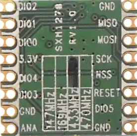
The LoRa RFM95 (Manufacturer Part ID: RFM95-915S2) is a low-power, long-range transceiver module manufactured by HopeRF. It operates in the sub-GHz frequency bands and is specifically designed for low-power wireless communication in IoT (Internet of Things) applications. The module utilizes LoRa modulation, which provides robust communication even in noisy environments, making it ideal for long-range, battery-operated devices.
Explore Projects Built with Lora Rfm95
 Open Project in Cirkit Designer
 Open Project in Cirkit Designer
 Open Project in Cirkit Designer
 Open Project in Cirkit Designer
Explore Projects Built with Lora Rfm95
Open Project in Cirkit DesignerOpen Project in Cirkit DesignerOpen Project in Cirkit DesignerOpen Project in Cirkit DesignerCommon Applications
- Smart agriculture (e.g., soil moisture sensors, weather stations)
- Industrial IoT (e.g., asset tracking, predictive maintenance)
- Smart cities (e.g., parking sensors, environmental monitoring)
- Home automation (e.g., smart meters, security systems)
- Remote monitoring and control systems
Technical Specifications
Key Technical Details
| Parameter | Value |
|---|---|
| Frequency Range | 902 MHz to 928 MHz (ISM Band) |
| Modulation | LoRa, FSK, GFSK |
| Output Power | Up to +20 dBm |
| Sensitivity | Down to -148 dBm |
| Data Rate | 0.018 kbps to 37.5 kbps (LoRa mode) |
| Supply Voltage | 1.8V to 3.7V |
| Current Consumption | 120 mA (TX at +20 dBm), 10.3 mA (RX mode) |
| Operating Temperature | -40°C to +85°C |
| Communication Interface | SPI |
| Dimensions | 16 mm x 16 mm x 2 mm |
Pin Configuration and Descriptions
The RFM95 module has 16 pins. Below is the pinout and description:
| Pin Number | Pin Name | Description |
|---|---|---|
| 1 | GND | Ground |
| 2 | DIO5 | Digital I/O Pin 5 |
| 3 | DIO4 | Digital I/O Pin 4 |
| 4 | DIO3 | Digital I/O Pin 3 |
| 5 | DIO2 | Digital I/O Pin 2 |
| 6 | DIO1 | Digital I/O Pin 1 |
| 7 | DIO0 | Digital I/O Pin 0 (Interrupt Pin) |
| 8 | NSS | SPI Chip Select |
| 9 | MISO | SPI Master-In-Slave-Out |
| 10 | MOSI | SPI Master-Out-Slave-In |
| 11 | SCK | SPI Clock |
| 12 | GND | Ground |
| 13 | 3.3V | Power Supply (1.8V to 3.7V) |
| 14 | RESET | Reset Pin |
| 15 | ANT | Antenna Connection |
| 16 | GND | Ground |
Usage Instructions
How to Use the RFM95 in a Circuit
- Power Supply: Connect the module to a regulated power supply of 3.3V. Ensure the supply voltage does not exceed 3.7V to avoid damaging the module.
- SPI Communication: Connect the SPI pins (NSS, MISO, MOSI, SCK) to the corresponding SPI pins on your microcontroller.
- Antenna: Attach a suitable antenna to the ANT pin for optimal range and performance.
- Digital I/O Pins: Use the DIO pins for interrupts or additional control signals as required by your application.
- Reset: Connect the RESET pin to your microcontroller or a manual reset button.
Important Considerations
- Antenna Matching: Use a properly matched antenna to ensure maximum range and efficiency.
- Power Consumption: Minimize power consumption by using the module's sleep mode when not transmitting or receiving.
- Regulatory Compliance: Ensure compliance with local regulations for ISM band usage.
- Noise Reduction: Place decoupling capacitors near the power supply pins to reduce noise.
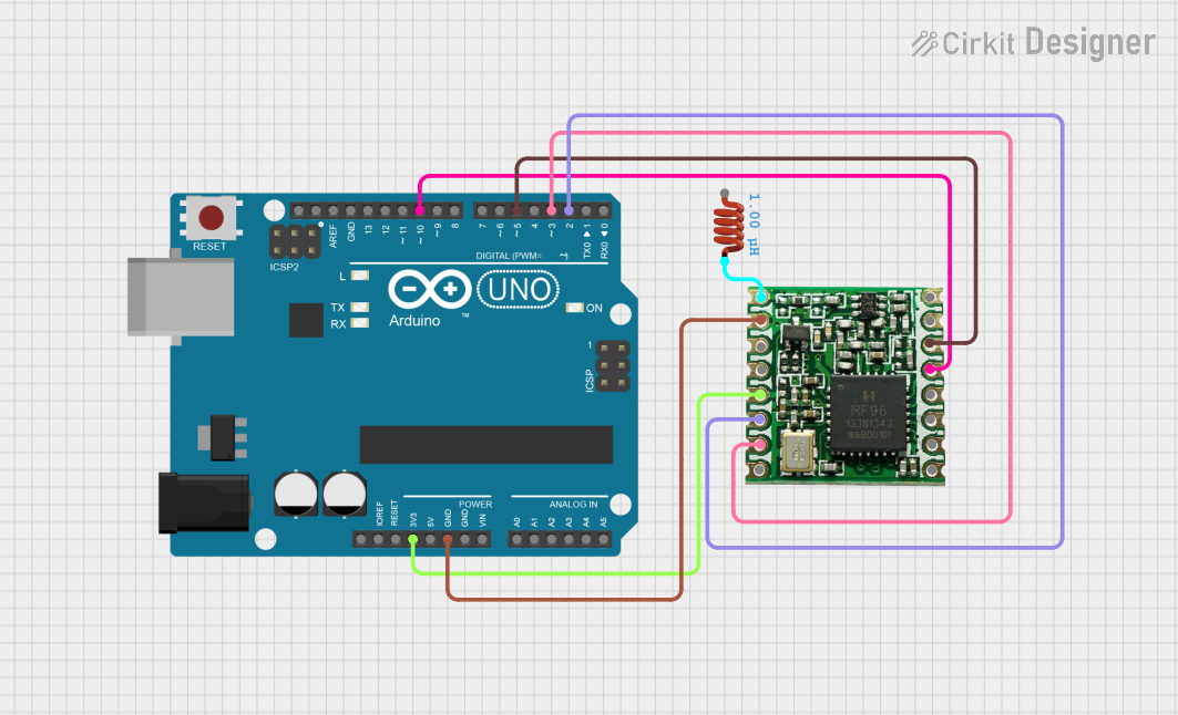
Example: Connecting RFM95 to Arduino UNO
Below is an example of how to connect the RFM95 to an Arduino UNO and send data using the LoRa library.
Wiring Diagram
| RFM95 Pin | Arduino UNO Pin |
|---|---|
| NSS | D10 |
| MOSI | D11 |
| MISO | D12 |
| SCK | D13 |
| DIO0 | D2 |
| RESET | D9 |
| 3.3V | 3.3V |
| GND | GND |
Arduino Code Example
#include <SPI.h>
#include <LoRa.h> // Include the LoRa library

#define NSS 10    // SPI Chip Select
#define RESET 9   // Reset Pin
#define DIO0 2    // Interrupt Pin

void setup() {
  Serial.begin(9600); // Initialize serial communication
  while (!Serial);

  Serial.println("Initializing LoRa module...");

  // Initialize LoRa module
  LoRa.setPins(NSS, RESET, DIO0);
  if (!LoRa.begin(915E6)) { // Set frequency to 915 MHz
    Serial.println("LoRa initialization failed!");
    while (1);
  }

  Serial.println("LoRa initialized successfully!");
}

void loop() {
  Serial.println("Sending packet...");
  LoRa.beginPacket();          // Start a new packet
  LoRa.print("Hello, LoRa!");  // Add data to the packet
  LoRa.endPacket();            // Send the packet

  delay(5000); // Wait 5 seconds before sending the next packet
}
Notes
- Install the LoRa library from the Arduino Library Manager before uploading the code.
- Adjust the frequency (
915E6) based on your region's ISM band regulations.
Troubleshooting and FAQs
Common Issues
Module Not Responding
- Cause: Incorrect wiring or power supply issues.
- Solution: Double-check all connections and ensure the module is powered with a stable 3.3V supply.
Poor Range
- Cause: Improper antenna or environmental interference.
- Solution: Use a properly matched antenna and test in an open area with minimal obstructions.
LoRa Initialization Fails
- Cause: Incorrect SPI connections or frequency mismatch.
- Solution: Verify SPI connections and ensure the frequency matches the module's specifications.
High Power Consumption
- Cause: Module not entering sleep mode.
- Solution: Use the sleep mode feature in your code when the module is idle.
FAQs
Q: Can the RFM95 operate at 5V?
A: No, the RFM95 operates at a maximum of 3.7V. Use a level shifter if interfacing with a 5V microcontroller.
Q: What is the maximum range of the RFM95?
A: The range can reach up to several kilometers in open space, depending on the antenna and environmental conditions.
Q: Can I use the RFM95 for FSK modulation?
A: Yes, the RFM95 supports FSK and GFSK modulation in addition to LoRa.
Q: Is the RFM95 compatible with LoRaWAN?
A: The RFM95 supports LoRa modulation, which is the basis for LoRaWAN. However, additional software or a LoRaWAN stack is required for full LoRaWAN compatibility.