How to Use STM-32 NUCLEO-F401RE: Examples, Pinouts, and Specs
Introduction
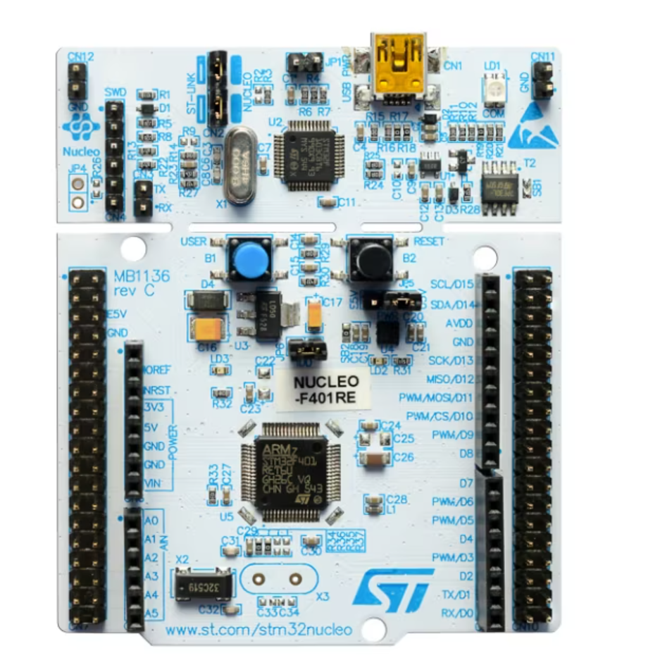
The STM-32 NUCLEO-F401RE is a development board manufactured by STMicroelectronics, featuring the STM32F401RE microcontroller. It is part of the STM32 family and is designed to facilitate rapid prototyping and development of embedded applications. The board supports both Arduino Uno V3 and ST morpho headers, making it highly versatile and compatible with a wide range of expansion boards and shields.
Explore Projects Built with STM-32 NUCLEO-F401RE
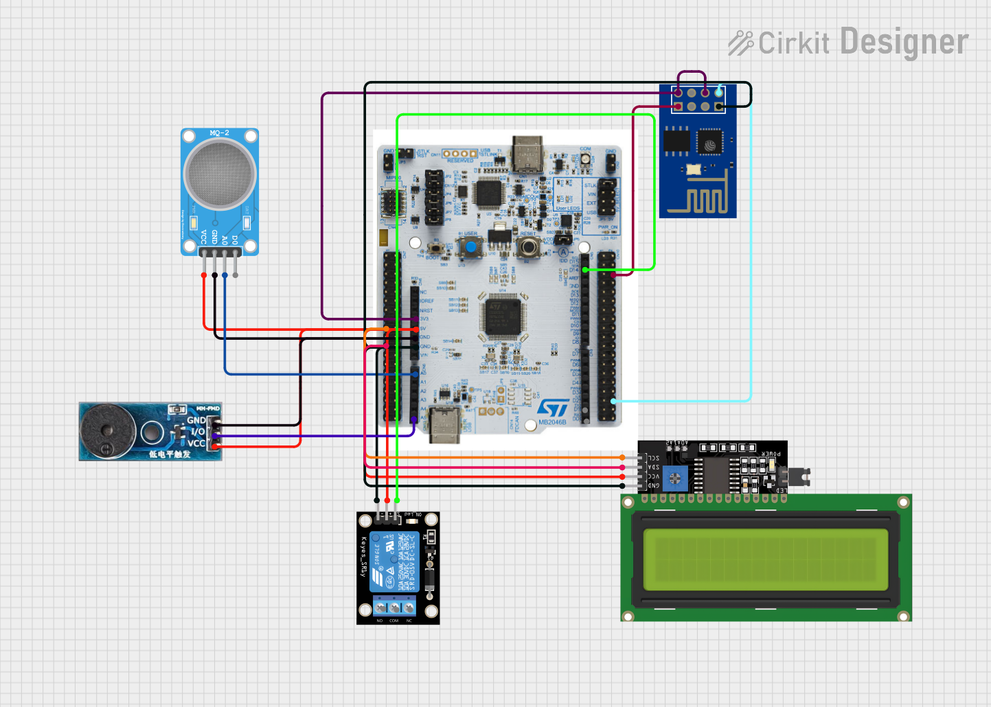


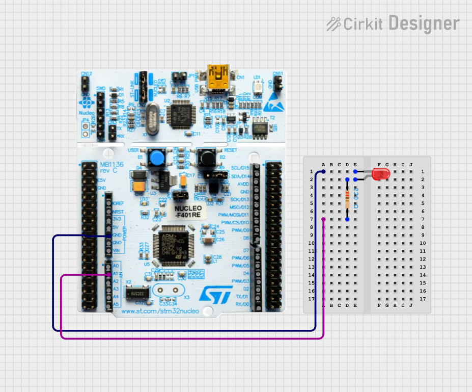
Explore Projects Built with STM-32 NUCLEO-F401RE
Common Applications and Use Cases
- Prototyping IoT devices
- Developing motor control systems
- Building sensor-based applications
- Educational purposes for learning embedded systems
- Rapid development of industrial automation solutions
Technical Specifications
Key Technical Details
- Microcontroller: STM32F401RE (ARM Cortex-M4, 32-bit, 84 MHz)
- Flash Memory: 512 KB
- SRAM: 96 KB
- Operating Voltage: 3.3V (core), 5V (I/O via Arduino headers)
- Input Voltage: 7V to 12V (via VIN pin or external power supply)
- Connectivity: USB (Micro-B), USART, I2C, SPI
- Clock Speed: 84 MHz
- Debugging Interface: ST-LINK/V2-1 (onboard)
- Dimensions: 68.6 mm x 53.3 mm
- Compatibility: Arduino Uno V3 headers, ST morpho headers
Pin Configuration and Descriptions
The STM-32 NUCLEO-F401RE features multiple pin headers for connectivity. Below is a summary of the pin configuration:
Arduino Uno V3 Header Pinout
| Pin Name | Function | Description |
|---|---|---|
| VIN | Power Input | External power input (7V-12V) |
| 5V | Power Output | 5V output from onboard regulator |
| 3.3V | Power Output | 3.3V output |
| GND | Ground | Ground connection |
| A0-A5 | Analog Input | 6 analog input pins |
| D0-D13 | Digital I/O | 14 digital I/O pins (D0-D1 for UART) |
| PWM | PWM Output | PWM-capable pins (e.g., D3, D5, D6, D9) |
| SDA/SCL | I2C Communication | I2C data (SDA) and clock (SCL) lines |
| RX/TX | UART Communication | UART receive (RX) and transmit (TX) pins |
ST Morpho Header Pinout
| Pin Name | Function | Description |
|---|---|---|
| VDD | Power Supply | 3.3V power supply |
| GND | Ground | Ground connection |
| PAx, PBx | GPIO | General-purpose I/O pins |
| USARTx | UART Communication | UART transmit and receive lines |
| SPIx | SPI Communication | SPI clock, MISO, MOSI, and NSS lines |
| I2Cx | I2C Communication | I2C data (SDA) and clock (SCL) lines |
| ADCx | Analog Input | Analog-to-digital converter inputs |
Usage Instructions
How to Use the Component in a Circuit
Powering the Board:
- Connect the board to your computer via the Micro-USB port for power and programming.
- Alternatively, use an external power supply (7V-12V) via the VIN pin or the barrel jack.
Programming the Board:
- Install the STM32CubeIDE or Arduino IDE with the STM32 core.
- Connect the board to your computer using a USB cable.
- Select the appropriate board and port in your IDE.
- Write and upload your code to the board.
Connecting Peripherals:
- Use the Arduino headers for shields or the ST morpho headers for custom peripherals.
- Ensure proper voltage levels and pin configurations for connected devices.
Debugging:
- Use the onboard ST-LINK/V2-1 debugger for real-time debugging and programming.
Important Considerations and Best Practices
- Ensure the input voltage does not exceed the specified range (7V-12V) to avoid damage.
- Use level shifters when interfacing 5V logic devices with the 3.3V GPIO pins.
- Avoid drawing excessive current from the 3.3V or 5V pins to prevent overheating.
- Always verify pin configurations and connections before powering the board.
Example Code for Arduino IDE
Below is an example code to blink an LED connected to pin D13:
// Blink an LED on pin D13 of the STM-32 NUCLEO-F401RE

void setup() {
  pinMode(13, OUTPUT); // Set pin D13 as an output
}

void loop() {
  digitalWrite(13, HIGH); // Turn the LED on
  delay(1000);            // Wait for 1 second
  digitalWrite(13, LOW);  // Turn the LED off
  delay(1000);            // Wait for 1 second
}
Troubleshooting and FAQs
Common Issues and Solutions
The board is not detected by the computer:
- Ensure the USB cable is functional and supports data transfer.
- Check that the ST-LINK drivers are installed on your computer.
Code upload fails:
- Verify that the correct board and port are selected in the IDE.
- Ensure no other application is using the COM port.
- Reset the board by pressing the reset button and try again.
Peripherals are not working as expected:
- Double-check the pin connections and configurations.
- Ensure the peripherals are compatible with the board's voltage levels.
The board overheats:
- Check for short circuits or excessive current draw from the power pins.
- Ensure the input voltage is within the specified range.
FAQs
Q: Can I use the STM-32 NUCLEO-F401RE with the Arduino IDE?
A: Yes, the board is compatible with the Arduino IDE. Install the STM32 core to program it using Arduino libraries.
Q: What is the maximum current output of the 3.3V and 5V pins?
A: The 3.3V pin can supply up to 100 mA, and the 5V pin can supply up to 500 mA when powered via USB.
Q: How do I reset the board?
A: Press the onboard reset button to restart the microcontroller.
Q: Can I use the board for low-power applications?
A: Yes, the STM32F401RE microcontroller supports low-power modes for energy-efficient applications.