How to Use DC ISOLATOR: Examples, Pinouts, and Specs
Introduction
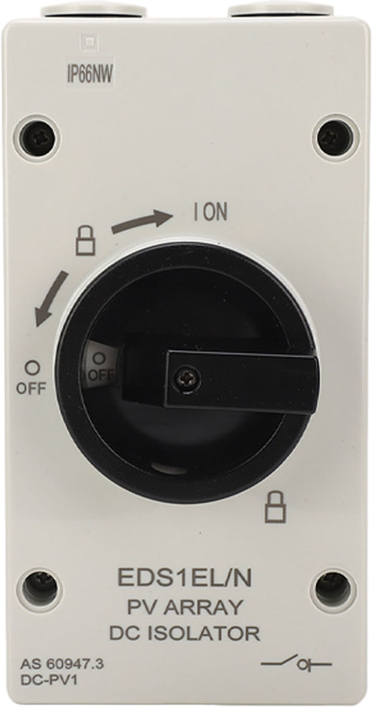
A DC isolator is a crucial safety device used to disconnect a direct current (DC) circuit from its power source. It ensures the safety of personnel and equipment during maintenance or in the event of a fault. DC isolators are commonly used in solar photovoltaic (PV) systems, battery storage systems, and other DC-powered applications to provide a reliable means of isolating circuits.
Explore Projects Built with DC ISOLATOR


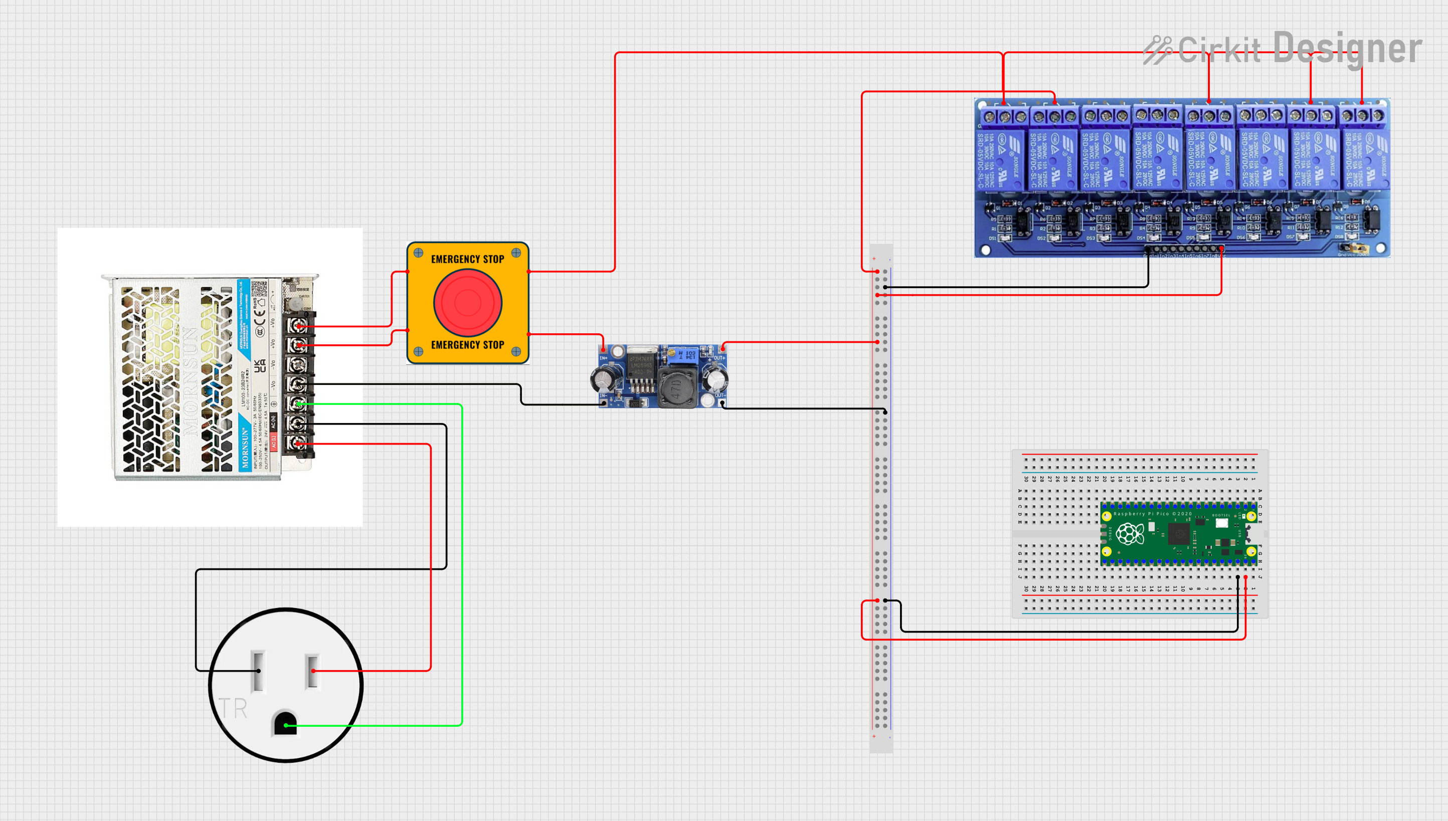
Explore Projects Built with DC ISOLATOR
Common Applications and Use Cases
- Solar PV systems: Disconnecting solar panels from inverters for maintenance.
- Battery storage systems: Isolating batteries for safety during servicing.
- Industrial DC circuits: Ensuring safe disconnection of DC motors or other equipment.
- Electric vehicles: Disconnecting high-voltage DC systems for repair or inspection.
Technical Specifications
Below are the key technical details of a typical DC isolator:
| Parameter | Value |
|---|---|
| Rated Voltage | 100 VDC to 1000 VDC (varies by model) |
| Rated Current | 16 A to 63 A (varies by model) |
| Poles | 2-pole or 4-pole |
| Operating Temperature | -25°C to +70°C |
| Enclosure Rating | IP65 (weatherproof for outdoor use) |
| Mounting Type | DIN rail or surface mount |
| Mechanical Endurance | 10,000 operations |
| Electrical Endurance | 1,000 operations at full load |
Pin Configuration and Descriptions
DC isolators typically have input and output terminals for connecting the DC power source and the load. Below is a general description of the terminal configuration:
| Terminal | Description |
|---|---|
| Input (+) | Positive terminal for the DC power source |
| Input (-) | Negative terminal for the DC power source |
| Output (+) | Positive terminal for the load |
| Output (-) | Negative terminal for the load |
| Ground (if available) | Optional grounding terminal for safety |
Usage Instructions
How to Use the DC Isolator in a Circuit
- Identify the Circuit: Determine the DC circuit you need to isolate, such as a solar PV system or battery bank.
- Select the Correct Isolator: Ensure the isolator's voltage and current ratings match or exceed the circuit's requirements.
- Connect the Terminals:
- Connect the DC power source to the input terminals of the isolator.
- Connect the load (e.g., inverter, battery) to the output terminals.
- If available, connect the ground terminal to the system ground for added safety.
- Mount the Isolator: Secure the isolator on a DIN rail or surface mount as per the installation requirements.
- Operate the Switch: Use the isolator's handle to switch between the ON and OFF positions. Ensure the switch is in the OFF position before performing maintenance.
Important Considerations and Best Practices
- Voltage and Current Ratings: Always use a DC isolator with ratings that meet or exceed the circuit's maximum voltage and current.
- Polarity: Ensure correct polarity when connecting the input and output terminals to avoid damage.
- Weatherproofing: For outdoor installations, use an isolator with an IP65 or higher enclosure rating.
- Lockout/Tagout: Use a lockable isolator to prevent accidental re-energization during maintenance.
- Regular Inspection: Periodically inspect the isolator for signs of wear, corrosion, or damage.
Example: Connecting a DC Isolator in a Solar PV System
Below is an example of how to connect a DC isolator between solar panels and an inverter:
Solar Panel (+) ----> DC Isolator Input (+)
Solar Panel (-) ----> DC Isolator Input (-)
DC Isolator Output (+) ----> Inverter Input (+)
DC Isolator Output (-) ----> Inverter Input (-)
Troubleshooting and FAQs
Common Issues and Solutions
Issue: The isolator does not disconnect the circuit.
- Solution: Verify that the isolator is in the OFF position. Check for internal damage or wear in the switch mechanism.
Issue: Overheating of the isolator during operation.
- Solution: Ensure the isolator's current rating matches the circuit's load. Replace the isolator if it is undersized.
Issue: Arcing when switching the isolator.
- Solution: Avoid switching under load if the isolator is not designed for load-breaking. Use a load-rated isolator for such applications.
Issue: Corrosion or damage to terminals.
- Solution: Inspect the isolator regularly, especially in outdoor installations. Use weatherproof enclosures and ensure proper sealing.
FAQs
Q1: Can a DC isolator be used for AC circuits?
A1: No, DC isolators are specifically designed for direct current. Using them in AC circuits may result in improper operation or damage.
Q2: How do I know if my DC isolator is weatherproof?
A2: Check the enclosure's IP rating. An IP65 or higher rating indicates weatherproofing suitable for outdoor use.
Q3: Can I install a DC isolator myself?
A3: While basic installations may be straightforward, it is recommended to consult a qualified electrician for safety and compliance with local regulations.
Q4: What is the difference between a 2-pole and a 4-pole DC isolator?
A4: A 2-pole isolator disconnects the positive and negative lines, while a 4-pole isolator can disconnect two separate circuits or provide additional safety in complex systems.