How to Use touch sensor: Examples, Pinouts, and Specs
Introduction
A touch sensor is a device that detects physical touch or proximity, often used in user interfaces to enable interaction with electronic devices. These sensors are widely used in modern electronics, such as smartphones, touchpads, and interactive displays. They provide a seamless and intuitive way for users to interact with devices without the need for mechanical buttons.
Explore Projects Built with touch sensor

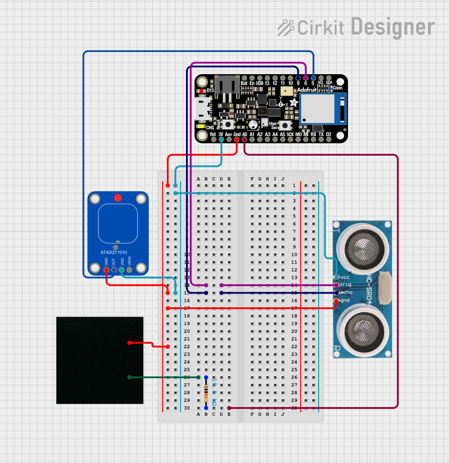
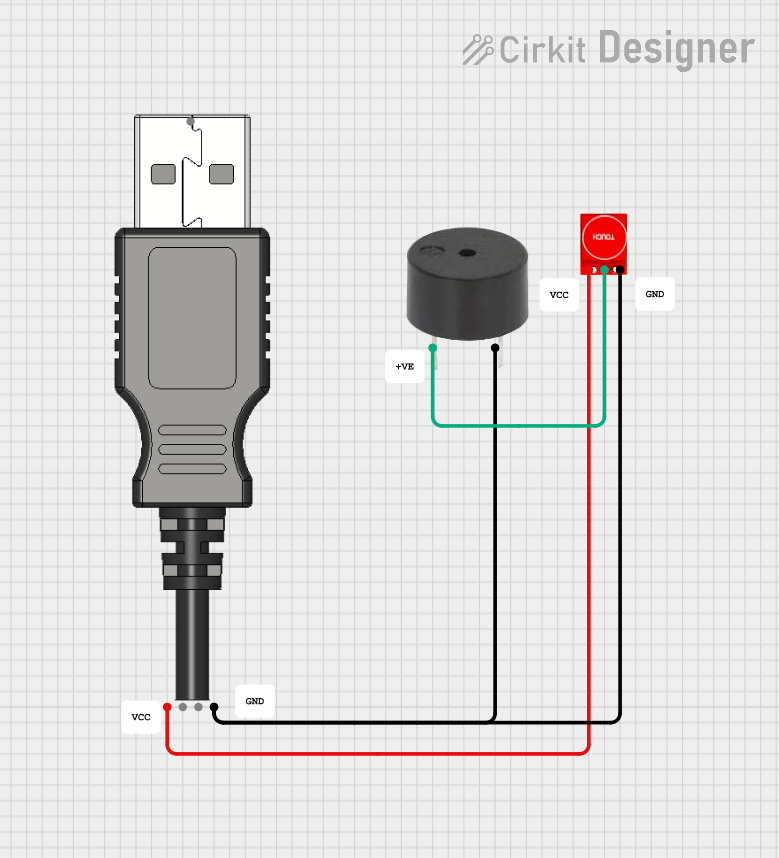
Explore Projects Built with touch sensor
Common Applications and Use Cases
- Capacitive touch buttons in consumer electronics
- Proximity detection in smart home devices
- Touch-sensitive lighting controls
- Interactive kiosks and displays
- Wearable devices and IoT applications
Technical Specifications
Below are the general technical specifications for a typical capacitive touch sensor module, such as the TTP223-based module:
| Parameter | Specification |
|---|---|
| Operating Voltage | 2.0V to 5.5V |
| Operating Current | < 3mA (active mode) |
| Response Time | ~60ms (fast mode), ~220ms (low power mode) |
| Output Type | Digital (High/Low) |
| Output Voltage (High) | VCC |
| Output Voltage (Low) | 0V |
| Touch Sensitivity | Adjustable (via onboard capacitor) |
| Dimensions | ~15mm x 11mm |
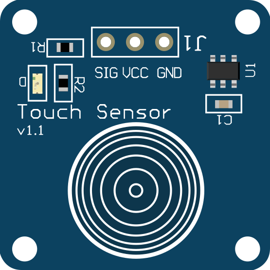
Pin Configuration and Descriptions
The touch sensor module typically has three pins:
| Pin Name | Description |
|---|---|
| VCC | Power supply pin (2.0V to 5.5V) |
| GND | Ground pin |
| OUT | Digital output pin (High when touched, Low otherwise) |
Usage Instructions
How to Use the Component in a Circuit
- Power the Sensor: Connect the
VCCpin to a 3.3V or 5V power source and theGNDpin to the ground of your circuit. - Connect the Output: Connect the
OUTpin to a microcontroller's digital input pin or any other circuit that needs to detect touch input. - Adjust Sensitivity (Optional): If the module has a sensitivity adjustment capacitor, you can modify it to increase or decrease the touch sensitivity.
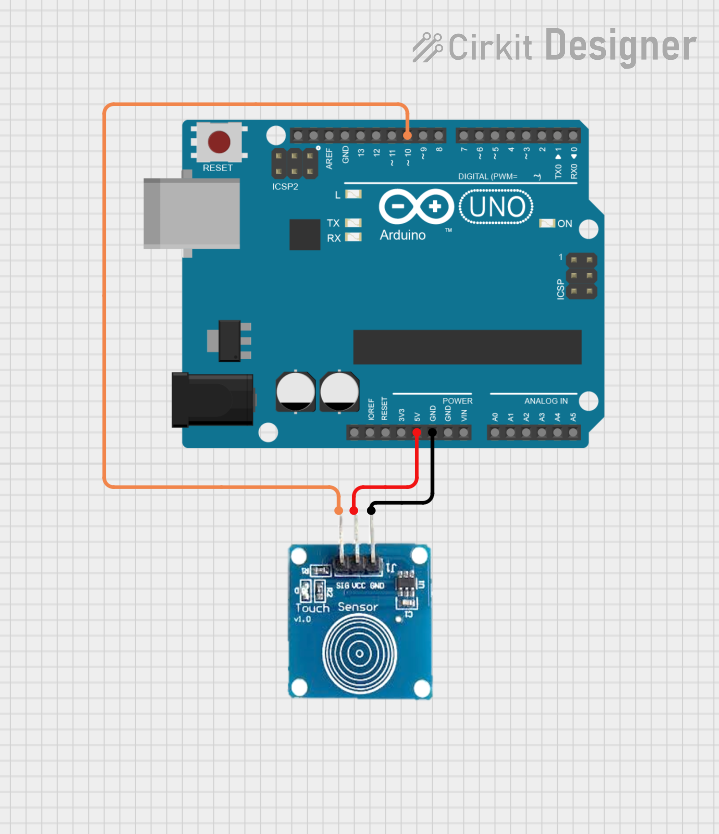
Example Circuit with Arduino UNO
Below is an example of how to connect a touch sensor to an Arduino UNO:
- Connect the
VCCpin of the touch sensor to the 5V pin on the Arduino. - Connect the
GNDpin of the touch sensor to the GND pin on the Arduino. - Connect the
OUTpin of the touch sensor to digital pin 2 on the Arduino.
Example Code for Arduino UNO
// Example code to use a touch sensor with Arduino UNO
// This code reads the touch sensor's output and turns on an LED when touched.

#define TOUCH_SENSOR_PIN 2  // Pin connected to the touch sensor's OUT pin
#define LED_PIN 13          // Pin connected to the onboard LED

void setup() {
  pinMode(TOUCH_SENSOR_PIN, INPUT);  // Set touch sensor pin as input
  pinMode(LED_PIN, OUTPUT);          // Set LED pin as output
  Serial.begin(9600);                // Initialize serial communication
}

void loop() {
  int touchState = digitalRead(TOUCH_SENSOR_PIN);  // Read the touch sensor state

  if (touchState == HIGH) {  // If the sensor is touched
    digitalWrite(LED_PIN, HIGH);  // Turn on the LED
    Serial.println("Touch detected!");  // Print message to serial monitor
  } else {
    digitalWrite(LED_PIN, LOW);  // Turn off the LED
  }

  delay(100);  // Small delay to stabilize readings
}
Important Considerations and Best Practices
- Power Supply: Ensure the sensor is powered within its operating voltage range to avoid damage.
- Debouncing: If the sensor output fluctuates, consider adding software debouncing in your code.
- Environmental Factors: Capacitive touch sensors can be affected by humidity, temperature, and nearby conductive materials. Test the sensor in its intended environment.
- Sensitivity Adjustment: If the sensor is too sensitive or not sensitive enough, adjust the onboard capacitor (if available) or modify the circuit design.
Troubleshooting and FAQs
Common Issues and Solutions
Sensor Not Responding
- Cause: Incorrect wiring or insufficient power supply.
- Solution: Double-check the connections and ensure the power supply voltage is within the specified range.
False Triggers
- Cause: Environmental noise or high sensitivity.
- Solution: Reduce sensitivity by adjusting the onboard capacitor or shielding the sensor from interference.
Output Stuck High or Low
- Cause: Faulty sensor or improper grounding.
- Solution: Verify the sensor's functionality with a multimeter and ensure a proper ground connection.
Slow Response Time
- Cause: Low power mode or high capacitance.
- Solution: Check the module's mode and reduce external capacitance if possible.
FAQs
Q1: Can I use the touch sensor with a 3.3V microcontroller?
A1: Yes, most touch sensors operate within a voltage range of 2.0V to 5.5V, making them compatible with 3.3V systems.
Q2: How do I increase the sensitivity of the touch sensor?
A2: You can increase sensitivity by adding a larger capacitor to the sensitivity adjustment pin (if available) or by reducing the distance between the sensor and the touch surface.
Q3: Can the touch sensor detect proximity without physical contact?
A3: Yes, capacitive touch sensors can detect proximity, but the range is limited and depends on the sensitivity settings.
Q4: Is the touch sensor waterproof?
A4: Most touch sensors are not waterproof by default. However, you can use a waterproof covering (e.g., glass or plastic) to protect the sensor while maintaining functionality.