How to Use Cloudrunner: Examples, Pinouts, and Specs
Introduction
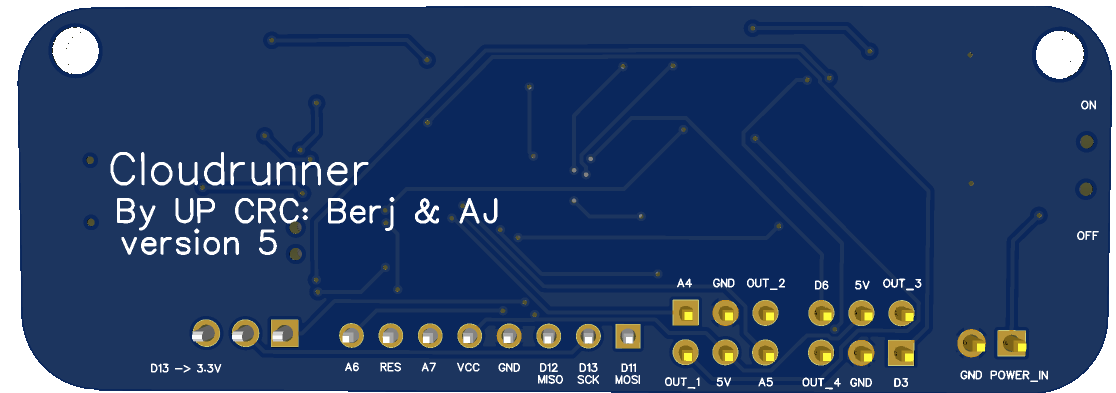
The Cloudrunner, manufactured by UP CRC, is a high-performance circuit component specifically designed for high-speed data transmission and processing in cloud computing environments. It is engineered to optimize network performance and resource allocation, making it an essential component in modern data centers and distributed computing systems. The Cloudrunner is ideal for applications requiring low-latency communication, efficient data handling, and robust scalability.
Explore Projects Built with Cloudrunner
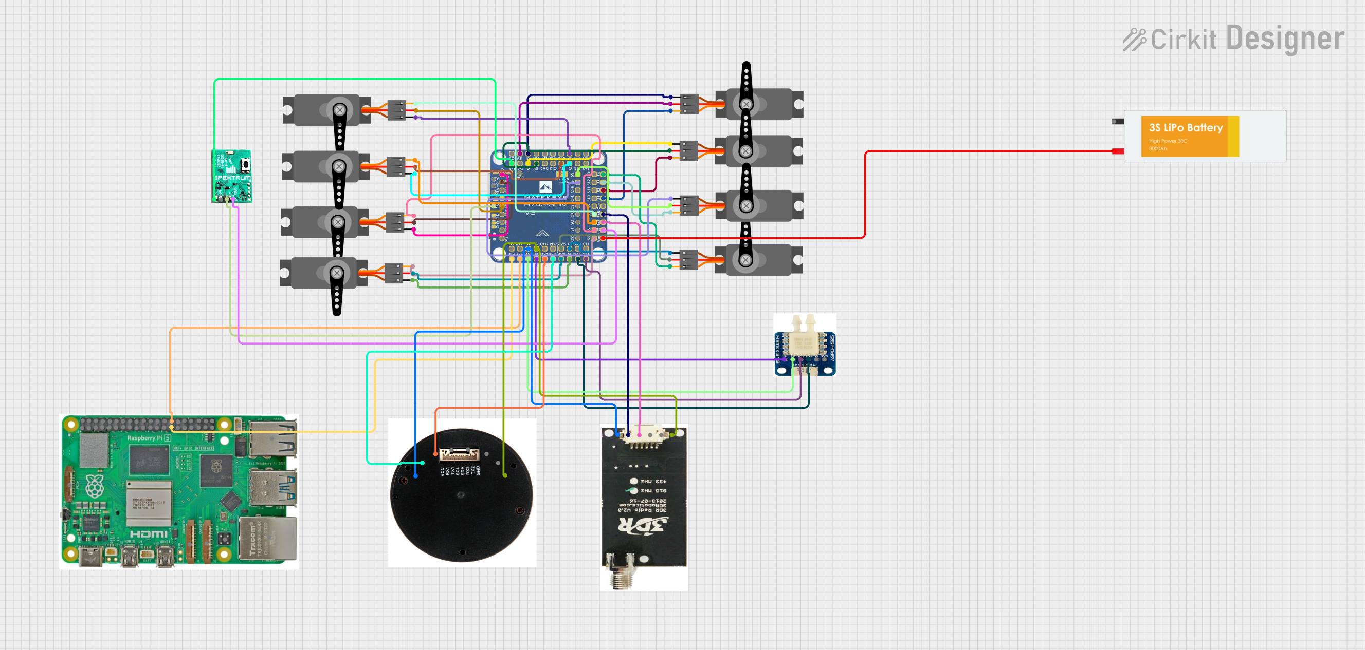

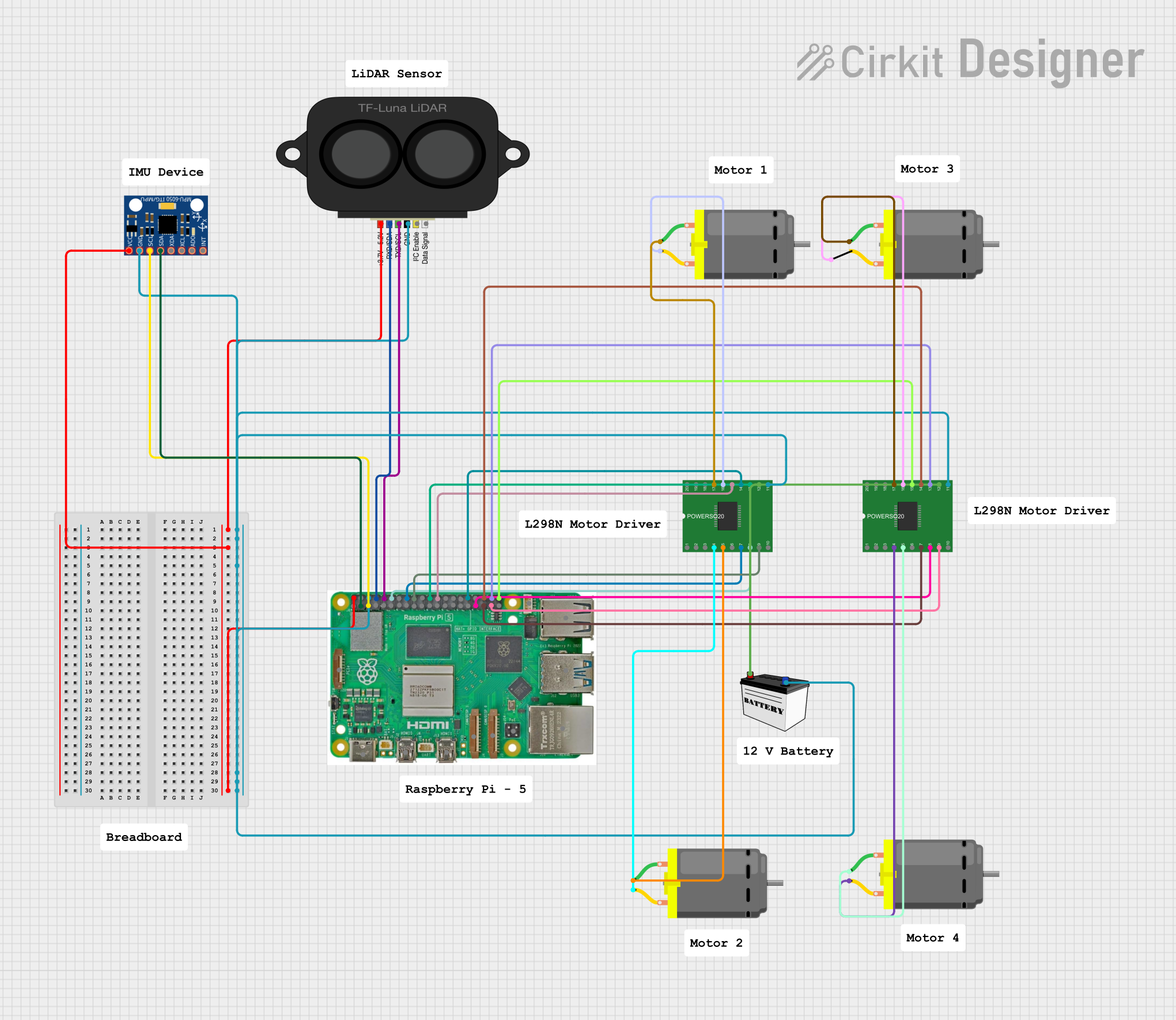
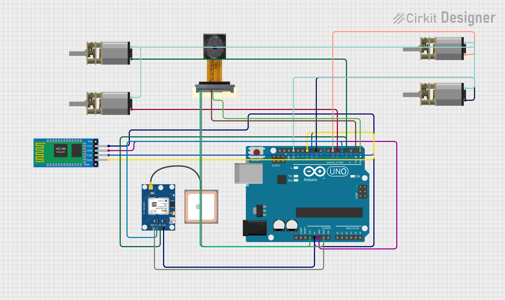
Explore Projects Built with Cloudrunner
Common Applications and Use Cases
- Cloud computing infrastructure
- High-speed data centers
- Distributed computing systems
- Network optimization hardware
- Edge computing devices
- AI and machine learning accelerators
Technical Specifications
The Cloudrunner is built to handle demanding workloads with precision and efficiency. Below are its key technical specifications:
General Specifications
| Parameter | Value |
|---|---|
| Operating Voltage | 3.3V to 5V |
| Maximum Current | 500mA |
| Data Transmission Rate | Up to 10 Gbps |
| Operating Temperature | -40°C to 85°C |
| Storage Temperature | -55°C to 125°C |
| Package Type | QFN-32 (Quad Flat No-lead) |
Pin Configuration and Descriptions
The Cloudrunner features a 32-pin QFN package. Below is the pin configuration:
| Pin Number | Pin Name | Description |
|---|---|---|
| 1 | VCC | Power supply input (3.3V to 5V) |
| 2 | GND | Ground connection |
| 3 | TX+ | Positive differential data transmission line |
| 4 | TX- | Negative differential data transmission line |
| 5 | RX+ | Positive differential data reception line |
| 6 | RX- | Negative differential data reception line |
| 7-10 | NC | Not connected |
| 11 | CLK_IN | Clock input for synchronization |
| 12 | RESET | Active-low reset pin |
| 13-16 | CONFIG[0:3] | Configuration pins for mode selection |
| 17-24 | DATA[0:7] | Data bus for parallel data input/output |
| 25 | INT | Interrupt output for signaling events |
| 26 | STATUS | Status output pin |
| 27 | ENABLE | Enable pin to activate the component |
| 28-32 | RESERVED | Reserved for future use |
Usage Instructions
The Cloudrunner is designed for seamless integration into high-speed data transmission systems. Follow the steps below to use the component effectively:
Basic Circuit Integration
- Power Supply: Connect the VCC pin to a stable 3.3V or 5V power source and the GND pin to the ground.
- Data Lines: Use the TX+ and TX- pins for transmitting data and the RX+ and RX- pins for receiving data. Ensure proper differential pair routing for minimal signal interference.
- Clock Input: Provide a stable clock signal to the CLK_IN pin for synchronization.
- Configuration: Set the CONFIG[0:3] pins to the desired mode of operation as per your application requirements.
- Reset and Enable: Use the RESET pin to initialize the component and the ENABLE pin to activate it.
Important Considerations
- Signal Integrity: Use high-quality PCB traces and impedance-controlled routing for differential pairs (TX+/TX- and RX+/RX-).
- Power Decoupling: Place decoupling capacitors (e.g., 0.1µF and 10µF) close to the VCC pin to minimize noise.
- Thermal Management: Ensure adequate heat dissipation, especially in high-speed applications, by using thermal vias or heat sinks.
- Mode Selection: Refer to the manufacturer's datasheet for detailed configuration settings using the CONFIG[0:3] pins.
Example: Using Cloudrunner with Arduino UNO
The Cloudrunner can be interfaced with an Arduino UNO for basic data transmission. Below is an example code snippet:
// Example: Interfacing Cloudrunner with Arduino UNO
// This code demonstrates basic initialization and data transmission.

// Define pin connections
#define ENABLE_PIN 7
#define RESET_PIN 8
#define STATUS_PIN 9
#define DATA_BUS_START 2  // Data bus starts at pin 2 (DATA[0])

void setup() {
  // Initialize serial communication for debugging
  Serial.begin(9600);

  // Configure pins
  pinMode(ENABLE_PIN, OUTPUT);
  pinMode(RESET_PIN, OUTPUT);
  pinMode(STATUS_PIN, INPUT);

  // Configure data bus pins as outputs
  for (int i = DATA_BUS_START; i < DATA_BUS_START + 8; i++) {
    pinMode(i, OUTPUT);
  }

  // Reset the Cloudrunner
  digitalWrite(RESET_PIN, LOW);
  delay(10);  // Hold reset for 10ms
  digitalWrite(RESET_PIN, HIGH);

  // Enable the Cloudrunner
  digitalWrite(ENABLE_PIN, HIGH);
  Serial.println("Cloudrunner initialized and enabled.");
}

void loop() {
  // Example: Send data over the data bus
  byte data = 0b10101010;  // Example data to send
  for (int i = 0; i < 8; i++) {
    digitalWrite(DATA_BUS_START + i, (data >> i) & 0x01);
  }

  // Check status pin
  if (digitalRead(STATUS_PIN) == HIGH) {
    Serial.println("Data transmission successful.");
  } else {
    Serial.println("Waiting for status...");
  }

  delay(1000);  // Wait for 1 second before sending the next data
}
Troubleshooting and FAQs
Common Issues and Solutions
No Data Transmission
- Cause: Incorrect power supply or loose connections.
- Solution: Verify the VCC and GND connections. Ensure the ENABLE pin is set high.
High Latency or Data Loss
- Cause: Poor signal integrity or improper differential pair routing.
- Solution: Use impedance-controlled PCB traces and minimize trace lengths for TX+/TX- and RX+/RX-.
Component Overheating
- Cause: Insufficient thermal management.
- Solution: Add heat sinks or improve PCB thermal design with thermal vias.
Reset Pin Not Working
- Cause: Incorrect reset sequence.
- Solution: Ensure the RESET pin is held low for at least 10ms before releasing.
FAQs
Q: Can the Cloudrunner operate at 1.8V?
- A: No, the Cloudrunner requires a minimum operating voltage of 3.3V.
Q: What is the maximum cable length for TX/RX lines?
- A: The maximum length depends on the transmission rate and cable quality. For 10 Gbps, use high-quality cables and keep lengths under 1 meter for optimal performance.
Q: Is the Cloudrunner compatible with SPI or I2C?
- A: No, the Cloudrunner uses a custom parallel data bus and differential signaling for high-speed communication.
This concludes the documentation for the Cloudrunner. For further details, refer to the official datasheet provided by UP CRC.