How to Use 5V-12V Step up Module: Examples, Pinouts, and Specs
Introduction
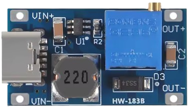
The 5V-12V Step Up Module is a DC-DC boost converter designed to increase a lower input voltage (e.g., 5V) to a higher output voltage (e.g., 12V). This module is widely used in applications where a device or circuit requires a higher voltage than what is available from the power source. It is compact, efficient, and ideal for powering devices such as LED strips, small motors, and microcontrollers that require a stable 12V supply.
Explore Projects Built with 5V-12V Step up Module


Explore Projects Built with 5V-12V Step up Module
Common Applications and Use Cases
- Powering 12V devices from USB power banks or 5V power supplies.
- Driving LED strips, fans, or small DC motors.
- Providing a stable 12V output for microcontroller-based projects.
- Battery-powered systems requiring voltage step-up functionality.
Technical Specifications
The following table outlines the key technical details of the 5V-12V Step Up Module:
| Parameter | Specification |
|---|---|
| Input Voltage Range | 2V to 24V |
| Output Voltage Range | Adjustable, typically 5V to 28V |
| Default Output Voltage | 12V |
| Maximum Output Current | 2A (varies based on input voltage) |
| Efficiency | Up to 93% |
| Dimensions | ~22mm x 17mm x 4mm |
| Operating Temperature | -40°C to +85°C |
Pin Configuration and Descriptions
The module typically has four pins or terminals for input and output connections. The table below describes each pin:
| Pin Name | Description |
|---|---|
| VIN+ | Positive input voltage (e.g., 5V) |
| VIN- | Negative input voltage (ground) |
| VOUT+ | Positive output voltage (e.g., 12V) |
| VOUT- | Negative output voltage (ground) |
Usage Instructions
How to Use the Component in a Circuit
Connect the Input Voltage:
- Connect the positive terminal of your power source (e.g., 5V) to the
VIN+pin. - Connect the ground terminal of your power source to the
VIN-pin.
- Connect the positive terminal of your power source (e.g., 5V) to the
Connect the Output Load:
- Connect the positive terminal of your load (e.g., a 12V device) to the
VOUT+pin. - Connect the ground terminal of your load to the
VOUT-pin.
- Connect the positive terminal of your load (e.g., a 12V device) to the
Adjust the Output Voltage (if applicable):
- Some modules include a small potentiometer for adjusting the output voltage.
- Use a multimeter to measure the output voltage while turning the potentiometer until the desired voltage (e.g., 12V) is achieved.
Power On:
- Once all connections are secure, power on the input source. The module will boost the input voltage to the desired output voltage.
Important Considerations and Best Practices
- Input Voltage Range: Ensure the input voltage is within the module's specified range (2V to 24V). Exceeding this range may damage the module.
- Output Current Limit: Do not exceed the maximum output current (2A). Overloading the module can cause overheating or failure.
- Heat Dissipation: For high-power applications, consider adding a heatsink or ensuring proper ventilation to prevent overheating.
- Polarity: Double-check the polarity of your connections. Reversing the input or output connections can damage the module.
- Voltage Adjustment: If the module includes a potentiometer, adjust it carefully to avoid overshooting the desired output voltage.
Example: Using the Module with an Arduino UNO
The 5V-12V Step Up Module can be used to power 12V peripherals in Arduino projects. Below is an example of connecting the module to an Arduino UNO and a 12V LED strip:
Circuit Connections:
- Connect the Arduino's 5V pin to the
VIN+pin of the module. - Connect the Arduino's GND pin to the
VIN-pin of the module. - Connect the
VOUT+pin of the module to the positive terminal of the 12V LED strip. - Connect the
VOUT-pin of the module to the negative terminal of the LED strip.
Example Code:
// Example code to control a 12V LED strip using an Arduino UNO
// The LED strip is powered via the 5V-12V Step Up Module

const int ledPin = 9; // PWM pin connected to the LED strip

void setup() {
  pinMode(ledPin, OUTPUT); // Set the LED pin as an output
}

void loop() {
  // Gradually increase brightness
  for (int brightness = 0; brightness <= 255; brightness++) {
    analogWrite(ledPin, brightness); // Set PWM duty cycle
    delay(10); // Small delay for smooth transition
  }

  // Gradually decrease brightness
  for (int brightness = 255; brightness >= 0; brightness--) {
    analogWrite(ledPin, brightness); // Set PWM duty cycle
    delay(10); // Small delay for smooth transition
  }
}
Troubleshooting and FAQs
Common Issues and Solutions
No Output Voltage:
- Cause: Incorrect wiring or insufficient input voltage.
- Solution: Verify all connections and ensure the input voltage is within the specified range.
Output Voltage is Incorrect:
- Cause: Potentiometer not adjusted or module is faulty.
- Solution: Use a multimeter to measure the output voltage and adjust the potentiometer as needed.
Module Overheating:
- Cause: Excessive load or poor ventilation.
- Solution: Reduce the load current or add a heatsink for better heat dissipation.
Device Not Powering On:
- Cause: Polarity issue or insufficient current.
- Solution: Double-check the polarity of all connections and ensure the input source can supply enough current.
FAQs
Q: Can I use this module to power a 12V motor?
A: Yes, as long as the motor's current draw does not exceed the module's maximum output current (2A).
Q: Is the output voltage stable?
A: Yes, the module provides a stable output voltage, but fluctuations may occur if the input voltage is unstable or the load exceeds the module's capacity.
Q: Can I use this module with a battery?
A: Yes, the module can step up the voltage from a battery, provided the battery's voltage is within the input range.
Q: How do I know if the module is overloaded?
A: Overloading may cause the module to overheat or shut down. Use a multimeter to measure the current and ensure it is within the specified limit.