How to Use max30102: Examples, Pinouts, and Specs
Introduction
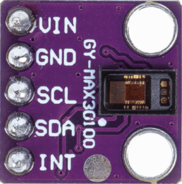
The MAX30102 is a pulse oximeter and heart-rate sensor module manufactured by Analog Devices (ADI) / Maxim Integrated. It utilizes photoplethysmography (PPG) technology to measure blood oxygen saturation (SpO2) and heart rate. The module integrates red and infrared LEDs, a photodetector, optical elements, and low-noise electronics in a compact package, making it ideal for wearable health monitoring devices.
Explore Projects Built with max30102


Explore Projects Built with max30102
Common Applications
- Wearable fitness trackers and smartwatches
- Medical devices for SpO2 and heart rate monitoring
- Health monitoring systems for IoT applications
- Research and development in biomedical engineering
Technical Specifications
The MAX30102 is designed for low-power operation and high performance in compact systems. Below are its key technical details:
Key Specifications
| Parameter | Value |
|---|---|
| Supply Voltage | 1.8V (core) and 3.3V (LEDs) |
| Operating Current | 600 µA (typical) |
| Standby Current | 0.7 µA |
| LED Wavelengths | Red: 660 nm, Infrared: 880 nm |
| Communication Interface | I²C (7-bit address: 0x15) |
| Sampling Rate | Configurable (up to 1000 samples per second) |
| Operating Temperature Range | -40°C to +85°C |
| Package Dimensions | 5.6 mm x 3.3 mm x 1.55 mm |
Pin Configuration
The MAX30102 has 8 pins, as described in the table below:
| Pin Number | Pin Name | Description |
|---|---|---|
| 1 | VIN | Power supply input (1.8V for core, 3.3V for LEDs) |
| 2 | GND | Ground |
| 3 | SDA | I²C data line |
| 4 | SCL | I²C clock line |
| 5 | INT | Interrupt output (active low) |
| 6 | RD | Red LED cathode |
| 7 | IR | Infrared LED cathode |
| 8 | NC | Not connected |
Usage Instructions
How to Use the MAX30102 in a Circuit
- Power Supply: Connect the VIN pin to a 1.8V power source for the core and a 3.3V source for the LEDs. Connect the GND pin to the ground of the circuit.
- I²C Communication: Connect the SDA and SCL pins to the corresponding I²C pins on your microcontroller. Use pull-up resistors (typically 4.7 kΩ) on both lines.
- Interrupt Pin: The INT pin can be connected to a GPIO pin on the microcontroller to handle interrupts for data-ready signals.
- LED Connections: The RD and IR pins are internally connected to the red and infrared LEDs, so no external connections are required.
- Bypass Capacitors: Place a 0.1 µF capacitor close to the VIN pin to stabilize the power supply.
Best Practices
- Use a low-noise power supply to ensure accurate measurements.
- Avoid placing the sensor near strong light sources to minimize interference.
- Ensure proper alignment of the sensor with the skin for optimal readings.
- Use the manufacturer's recommended initialization sequence for the I²C interface.
Example Code for Arduino UNO
Below is an example of how to interface the MAX30102 with an Arduino UNO to read heart rate and SpO2 data:
#include <Wire.h>
#include "MAX30102.h" // Include a library for MAX30102 (e.g., SparkFun MAX3010x)

MAX30102 sensor; // Create an instance of the MAX30102 class

void setup() {
  Serial.begin(9600); // Initialize serial communication at 9600 baud
  Wire.begin();       // Initialize I²C communication

  if (sensor.begin() == false) {
    Serial.println("MAX30102 not detected. Check connections.");
    while (1); // Halt execution if the sensor is not detected
  }

  Serial.println("MAX30102 initialized successfully.");
}

void loop() {
  int heartRate = sensor.getHeartRate(); // Read heart rate
  int spo2 = sensor.getSpO2();          // Read SpO2 level

  if (heartRate != -1 && spo2 != -1) { // Check if readings are valid
    Serial.print("Heart Rate: ");
    Serial.print(heartRate);
    Serial.print(" bpm, SpO2: ");
    Serial.print(spo2);
    Serial.println(" %");
  } else {
    Serial.println("Error reading data. Ensure proper sensor placement.");
  }

  delay(1000); // Wait 1 second before the next reading
}
Notes
- The above code assumes the use of a compatible MAX30102 library. Install a library such as the SparkFun MAX3010x library via the Arduino Library Manager.
- Ensure the I²C address (0x15) matches the library's default or is configured correctly.
Troubleshooting and FAQs
Common Issues
Sensor Not Detected
- Cause: Incorrect I²C wiring or address mismatch.
- Solution: Verify SDA and SCL connections. Ensure pull-up resistors are in place. Check that the I²C address is set to 0x15.
Inaccurate Readings
- Cause: Poor sensor placement or external light interference.
- Solution: Ensure the sensor is in direct contact with the skin. Shield the sensor from ambient light.
No Data Output
- Cause: Improper initialization or power supply issues.
- Solution: Check the power supply voltage levels. Ensure the sensor is initialized correctly in the code.
FAQs
Can the MAX30102 measure SpO2 and heart rate simultaneously?
- Yes, the MAX30102 can measure both parameters simultaneously using its dual LED and photodetector setup.
What is the maximum sampling rate of the MAX30102?
- The MAX30102 supports a configurable sampling rate of up to 1000 samples per second.
Is the MAX30102 suitable for continuous monitoring?
- Yes, the MAX30102 is designed for low-power operation, making it suitable for continuous monitoring in wearable devices.
Can the MAX30102 be used with a 5V microcontroller?
- Yes, but you must use a level shifter for the I²C lines, as the MAX30102 operates at 1.8V logic levels.