Cirkit Designer Logo
Cirkit Designer
Your all-in-one circuit design IDE
Home / 
Component Documentation

How to Use ESP32: Examples, Pinouts, and Specs

Image of ESP32
Cirkit Designer LogoDesign with ESP32 in Cirkit Designer

Introduction

The ESP32 is a powerful microcontroller with integrated Wi-Fi and Bluetooth capabilities, making it an ideal choice for Internet of Things (IoT) applications and embedded systems. It is designed to provide high performance, low power consumption, and versatile connectivity options. The ESP32 is widely used in smart home devices, wearable electronics, industrial automation, and wireless sensor networks.

Explore Projects Built with ESP32

Use Cirkit Designer to design, explore, and prototype these projects online. Some projects support real-time simulation. Click "Open Project" to start designing instantly!
ESP32-Based Sensor Monitoring System with OLED Display and E-Stop
Image of MVP_design: A project utilizing ESP32 in a practical application
This circuit features an ESP32 microcontroller that interfaces with a variety of sensors and output devices. It is powered by a Lipo battery through a buck converter, ensuring a stable voltage supply. The ESP32 collects data from a DHT11 temperature and humidity sensor and a vibration sensor, controls a buzzer, and displays information on an OLED screen. An emergency stop (E Stop) is connected for safety purposes, allowing the system to be quickly deactivated.
Cirkit Designer LogoOpen Project in Cirkit Designer
ESP32-Based NTP Clock with DHT22 Temperature Sensor and WS2812 LED Matrix Display
Image of date time and temperature display : A project utilizing ESP32 in a practical application
This circuit features an ESP32 Devkit V1 microcontroller connected to a DHT22 temperature and humidity sensor and an 8x8 WS2812 RGB LED matrix. The ESP32 reads temperature data from the DHT22 sensor and displays the current date, time, and temperature on the LED matrix, with date and time synchronized via NTP (Network Time Protocol). The ESP32 provides power to both the DHT22 and the LED matrix and communicates with the DHT22 via GPIO 4 and with the LED matrix via GPIO 5.
Cirkit Designer LogoOpen Project in Cirkit Designer
ESP32-Based Environmental Monitoring System with Water Flow Sensing
Image of Water: A project utilizing ESP32 in a practical application
This circuit features an ESP32 Devkit V1 microcontroller connected to a DHT22 temperature and humidity sensor and a water flow sensor. The ESP32 reads environmental data from the DHT22 via a digital input pin (D33) and monitors water flow through the water flow sensor connected to another digital input pin (D23). The ESP32 is powered through its VIN pin, and both sensors are powered by the ESP32's 3V3 output, with common ground connections.
Cirkit Designer LogoOpen Project in Cirkit Designer
ESP32-Based Smart Weather Station with Wi-Fi Connectivity
Image of flowchart 3D: A project utilizing ESP32 in a practical application
This circuit features an ESP32 microcontroller interfacing with various sensors and modules, including a DHT22 temperature and humidity sensor, an ESP32 CAM for image capture, an I2C LCD screen for display, a load cell with an HX711 interface for weight measurement, and a buzzer for audio alerts. The ESP32 handles data acquisition, processing, and communication with these peripherals to create a multi-functional monitoring and alert system.
Cirkit Designer LogoOpen Project in Cirkit Designer

Explore Projects Built with ESP32

Use Cirkit Designer to design, explore, and prototype these projects online. Some projects support real-time simulation. Click "Open Project" to start designing instantly!
Image of MVP_design: A project utilizing ESP32 in a practical application
ESP32-Based Sensor Monitoring System with OLED Display and E-Stop
This circuit features an ESP32 microcontroller that interfaces with a variety of sensors and output devices. It is powered by a Lipo battery through a buck converter, ensuring a stable voltage supply. The ESP32 collects data from a DHT11 temperature and humidity sensor and a vibration sensor, controls a buzzer, and displays information on an OLED screen. An emergency stop (E Stop) is connected for safety purposes, allowing the system to be quickly deactivated.
Cirkit Designer LogoOpen Project in Cirkit Designer
Image of date time and temperature display : A project utilizing ESP32 in a practical application
ESP32-Based NTP Clock with DHT22 Temperature Sensor and WS2812 LED Matrix Display
This circuit features an ESP32 Devkit V1 microcontroller connected to a DHT22 temperature and humidity sensor and an 8x8 WS2812 RGB LED matrix. The ESP32 reads temperature data from the DHT22 sensor and displays the current date, time, and temperature on the LED matrix, with date and time synchronized via NTP (Network Time Protocol). The ESP32 provides power to both the DHT22 and the LED matrix and communicates with the DHT22 via GPIO 4 and with the LED matrix via GPIO 5.
Cirkit Designer LogoOpen Project in Cirkit Designer
Image of Water: A project utilizing ESP32 in a practical application
ESP32-Based Environmental Monitoring System with Water Flow Sensing
This circuit features an ESP32 Devkit V1 microcontroller connected to a DHT22 temperature and humidity sensor and a water flow sensor. The ESP32 reads environmental data from the DHT22 via a digital input pin (D33) and monitors water flow through the water flow sensor connected to another digital input pin (D23). The ESP32 is powered through its VIN pin, and both sensors are powered by the ESP32's 3V3 output, with common ground connections.
Cirkit Designer LogoOpen Project in Cirkit Designer
Image of flowchart 3D: A project utilizing ESP32 in a practical application
ESP32-Based Smart Weather Station with Wi-Fi Connectivity
This circuit features an ESP32 microcontroller interfacing with various sensors and modules, including a DHT22 temperature and humidity sensor, an ESP32 CAM for image capture, an I2C LCD screen for display, a load cell with an HX711 interface for weight measurement, and a buzzer for audio alerts. The ESP32 handles data acquisition, processing, and communication with these peripherals to create a multi-functional monitoring and alert system.
Cirkit Designer LogoOpen Project in Cirkit Designer

Technical Specifications

The ESP32 is equipped with a dual-core processor, a rich set of peripherals, and advanced connectivity features. Below are its key technical specifications:

General Specifications

  • Processor: Dual-core Xtensa® 32-bit LX6 microprocessor
  • Clock Speed: Up to 240 MHz
  • Flash Memory: 4 MB (varies by model)
  • SRAM: 520 KB
  • Wi-Fi: 802.11 b/g/n
  • Bluetooth: v4.2 BR/EDR and BLE
  • Operating Voltage: 3.3V
  • GPIO Pins: 34 (multipurpose)

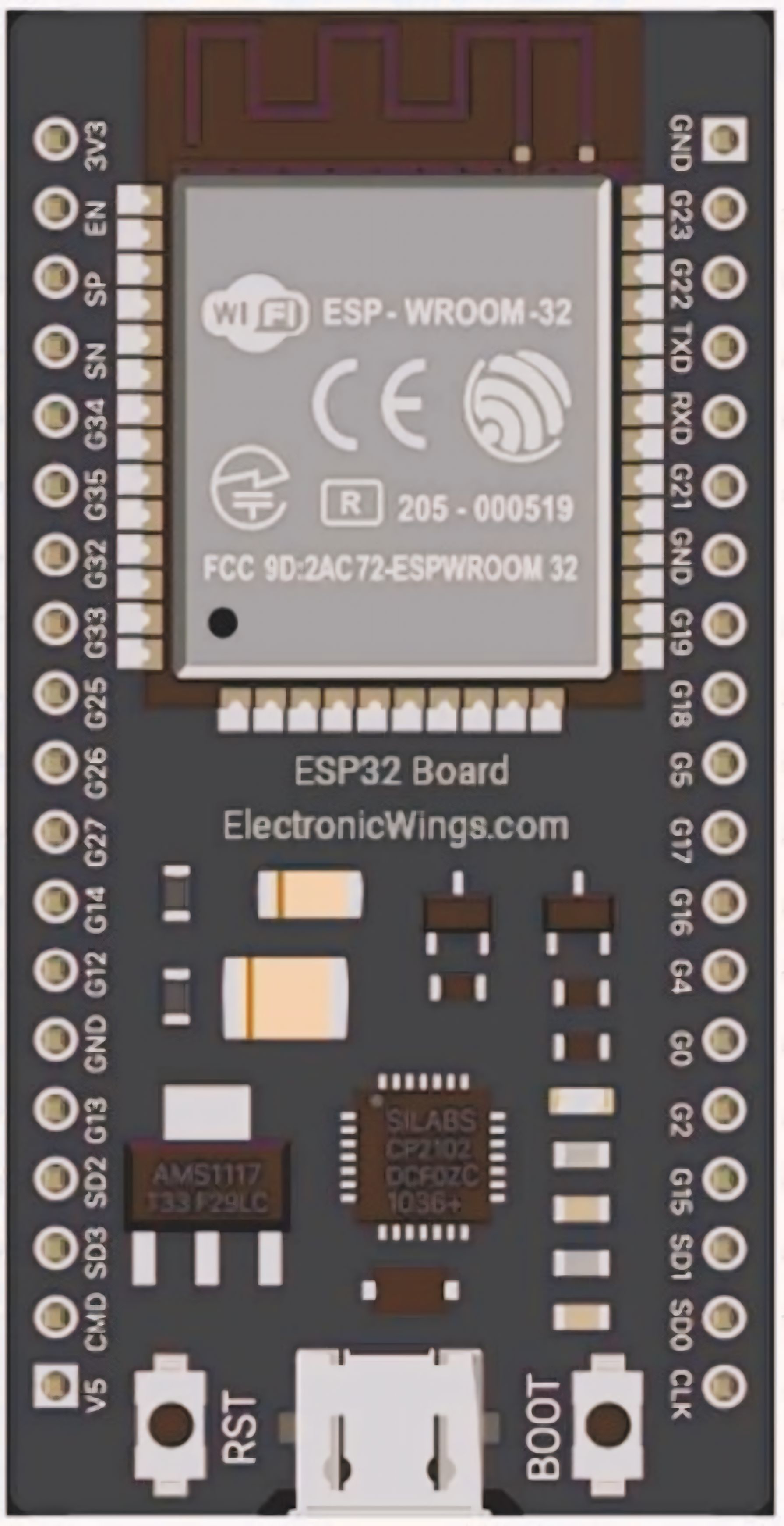
Pin Configuration and Descriptions

The ESP32 has multiple pins for various functionalities. Below is a table summarizing the key pins:

Pin Name Function Description
GPIO0 Input/Output, Boot Mode Used for general I/O or to enter bootloader mode during programming.
GPIO2 Input/Output, ADC, PWM General-purpose I/O, supports ADC and PWM functionalities.
GPIO12 Input/Output, ADC, Touch General-purpose I/O, supports ADC and capacitive touch sensing.
GPIO13 Input/Output, ADC, Touch General-purpose I/O, supports ADC and capacitive touch sensing.
GPIO15 Input/Output, ADC, PWM General-purpose I/O, supports ADC and PWM functionalities.
EN Enable Active-high pin to enable or reset the chip.
3V3 Power Provides 3.3V power output.
GND Ground Ground connection.
TX0 UART Transmit UART0 transmit pin for serial communication.
RX0 UART Receive UART0 receive pin for serial communication.

Note: The ESP32 has multiple ADC, PWM, and UART pins. Refer to the datasheet for a complete pinout.

Usage Instructions

The ESP32 can be used in a variety of circuits and projects. Below are the steps to get started:

Connecting the ESP32 to a Circuit

  1. Power Supply: Connect the 3.3V pin to a stable 3.3V power source and GND to ground.
  2. Programming: Use a USB-to-serial adapter or a development board with a built-in USB interface to program the ESP32.
  3. GPIO Usage: Connect peripherals (e.g., sensors, LEDs) to the GPIO pins. Ensure the voltage levels are compatible with the ESP32's 3.3V logic.

Programming the ESP32 with Arduino IDE

  1. Install the ESP32 board package in the Arduino IDE:
    • Go to File > Preferences and add the following URL to the "Additional Board Manager URLs" field:
      https://dl.espressif.com/dl/package_esp32_index.json
    • Open Tools > Board > Boards Manager, search for "ESP32," and install the package.
  2. Select the ESP32 board from Tools > Board.
  3. Connect the ESP32 to your computer via USB and select the correct COM port under Tools > Port.
  4. Write and upload your code.

Example Code: Blinking an LED

The following code demonstrates how to blink an LED connected to GPIO2:

// Define the GPIO pin where the LED is connected
const int ledPin = 2;

void setup() {
  // Set the LED pin as an output
  pinMode(ledPin, OUTPUT);
}

void loop() {
  // Turn the LED on
  digitalWrite(ledPin, HIGH);
  delay(1000); // Wait for 1 second

  // Turn the LED off
  digitalWrite(ledPin, LOW);
  delay(1000); // Wait for 1 second
}

Important: Ensure the LED is connected to GPIO2 with a current-limiting resistor (e.g., 220Ω) to prevent damage.

Best Practices

  • Use a level shifter if interfacing with 5V logic devices.
  • Avoid drawing excessive current from the GPIO pins (maximum 12mA per pin).
  • Use decoupling capacitors near the power pins to stabilize the power supply.

Troubleshooting and FAQs

Common Issues

  1. ESP32 Not Detected by Computer:

    • Ensure the USB cable is functional and supports data transfer.
    • Install the correct USB-to-serial driver for your development board.
  2. Upload Fails with "Timed Out" Error:

    • Press and hold the BOOT button on the ESP32 while uploading the code.
    • Check the selected COM port and board type in the Arduino IDE.
  3. Wi-Fi Connection Fails:

    • Verify the SSID and password in your code.
    • Ensure the Wi-Fi network is within range and supports 2.4 GHz (ESP32 does not support 5 GHz).

FAQs

  • Q: Can the ESP32 operate on 5V?
    A: No, the ESP32 operates at 3.3V. Applying 5V to GPIO pins can damage the chip.

  • Q: How do I reset the ESP32?
    A: Press the EN button on the development board to reset the ESP32.

  • Q: Can I use the ESP32 for battery-powered projects?
    A: Yes, the ESP32 supports low-power modes, making it suitable for battery-powered applications.

By following this documentation, you can effectively use the ESP32 in your projects and troubleshoot common issues. For advanced features, refer to the official ESP32 datasheet and programming guide.