How to Use Eltako MFZ12DDX-UC: Examples, Pinouts, and Specs
Introduction
The Eltako MFZ12DDX-UC is a multifunctional relay module designed for controlling a wide range of electrical devices. Its compact design ensures seamless integration into existing systems, making it a versatile choice for automation projects. This relay module supports multiple input and output configurations, offering flexibility for various applications. With its reliable switching capabilities and energy-efficient operation, the MFZ12DDX-UC is ideal for use in smart homes, industrial automation, and other control systems.
Explore Projects Built with Eltako MFZ12DDX-UC

Explore Projects Built with Eltako MFZ12DDX-UC
Common Applications and Use Cases
- Smart home automation (e.g., lighting, HVAC control)
- Industrial machinery control
- Energy management systems
- Time-controlled switching of electrical devices
- Integration into building management systems
Technical Specifications
Key Technical Details
| Parameter | Value |
|---|---|
| Operating Voltage | 8-230V AC/DC |
| Power Consumption | <1W |
| Switching Capacity | 16A / 250V AC |
| Control Input | Universal control voltage (8-230V AC/DC) |
| Relay Type | Potential-free changeover contact |
| Dimensions | 18mm width (1 module) |
| Mounting | DIN rail (EN 60715) |
| Operating Temperature | -20°C to +55°C |
| Protection Class | IP20 |
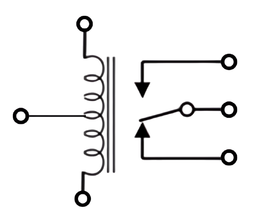
Pin Configuration and Descriptions
The Eltako MFZ12DDX-UC features the following terminal connections:
| Terminal | Description |
|---|---|
| A1 | Control input (universal voltage: 8-230V AC/DC) |
| A2 | Control input ground |
| 15 | Common terminal for the relay |
| 16 | Normally open (NO) contact |
| 18 | Normally closed (NC) contact |
Usage Instructions
How to Use the Component in a Circuit
- Power Supply: Connect the module to a power source within the operating voltage range (8-230V AC/DC). Ensure proper polarity when using DC voltage.
- Control Input: Use terminals A1 and A2 to connect the control signal. The module supports a wide range of control voltages, making it compatible with various systems.
- Load Connection: Connect the load to the relay terminals (15, 16, and 18) based on the desired switching configuration:
- For normally open (NO) operation, use terminals 15 and 16.
- For normally closed (NC) operation, use terminals 15 and 18.
- Mounting: Install the module on a DIN rail for secure and stable operation.
- Configuration: Use the rotary switches on the module to set the desired function and time delay. Refer to the module's function chart for specific settings.
Important Considerations and Best Practices
- Ensure the total load does not exceed the relay's maximum switching capacity (16A at 250V AC).
- Use proper wire gauges and secure connections to prevent overheating or loose contacts.
- Avoid exposing the module to extreme temperatures or moisture to maintain reliable operation.
- When integrating with microcontrollers (e.g., Arduino), use an optocoupler or relay driver circuit to isolate the control signal.
Example: Connecting to an Arduino UNO
To control the MFZ12DDX-UC with an Arduino UNO, follow these steps:
- Connect the Arduino's digital output pin to the control input (A1) of the relay module.
- Connect the Arduino's ground (GND) to the control input ground (A2).
- Use a suitable power source for the relay module, ensuring it matches the operating voltage.
Here is an example Arduino code to toggle the relay:
// Define the pin connected to the relay control input
const int relayPin = 7;

void setup() {
  // Set the relay pin as an output
  pinMode(relayPin, OUTPUT);

  // Initialize the relay in the OFF state
  digitalWrite(relayPin, LOW);
}

void loop() {
  // Turn the relay ON
  digitalWrite(relayPin, HIGH);
  delay(5000); // Keep the relay ON for 5 seconds

  // Turn the relay OFF
  digitalWrite(relayPin, LOW);
  delay(5000); // Keep the relay OFF for 5 seconds
}
Notes:
- Use a flyback diode across the relay coil if the control signal is directly connected to the Arduino to protect against voltage spikes.
- Ensure the Arduino's output pin can handle the current required to drive the relay. If not, use a transistor or relay driver circuit.
Troubleshooting and FAQs
Common Issues and Solutions
Relay Not Switching
- Cause: Insufficient control voltage or incorrect wiring.
- Solution: Verify the control voltage at terminals A1 and A2. Check the wiring and ensure proper connections.
Overheating
- Cause: Exceeding the relay's maximum switching capacity.
- Solution: Reduce the load or use a relay with a higher capacity.
Unstable Operation
- Cause: Electrical noise or interference.
- Solution: Use shielded cables for control signals and ensure proper grounding.
No Response from the Module
- Cause: Faulty power supply or damaged module.
- Solution: Check the power supply voltage and replace the module if necessary.
FAQs
Q: Can the MFZ12DDX-UC be used with DC loads?
A: Yes, the relay supports both AC and DC loads, provided the load does not exceed the maximum switching capacity.
Q: How do I set the time delay function?
A: Use the rotary switches on the module to configure the desired time delay. Refer to the function chart in the product manual for specific settings.
Q: Is the module compatible with 3.3V control signals?
A: Yes, the module supports control voltages as low as 8V. However, ensure the control signal provides sufficient current to activate the relay.
Q: Can I use the relay for motor control?
A: Yes, but ensure the motor's inrush current does not exceed the relay's maximum switching capacity. Use a contactor for high-power motors.