
How to Use RF24G Header: Examples, Pinouts, and Specs
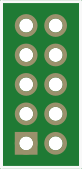
 Design with RF24G Header in Cirkit Designer
Introduction
The RF24G Header is a specialized connector designed for interfacing RF24G wireless modules with other circuit components. It provides a reliable and efficient way to establish communication between the RF24G module and microcontrollers or other devices. This header simplifies the integration of RF24G modules into various projects, ensuring stable connections and ease of use.
Explore Projects Built with RF24G Header
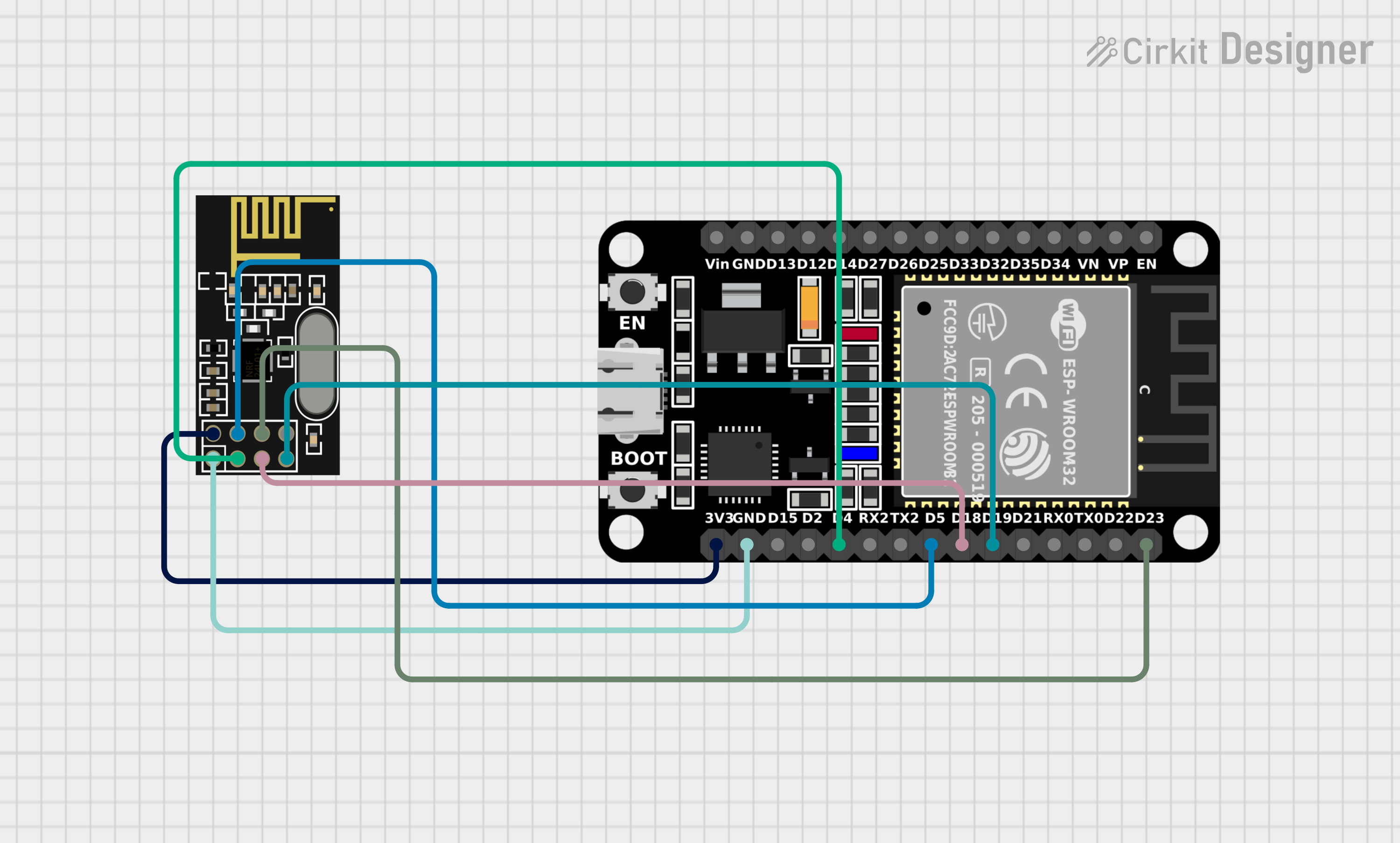 Open Project in Cirkit Designer
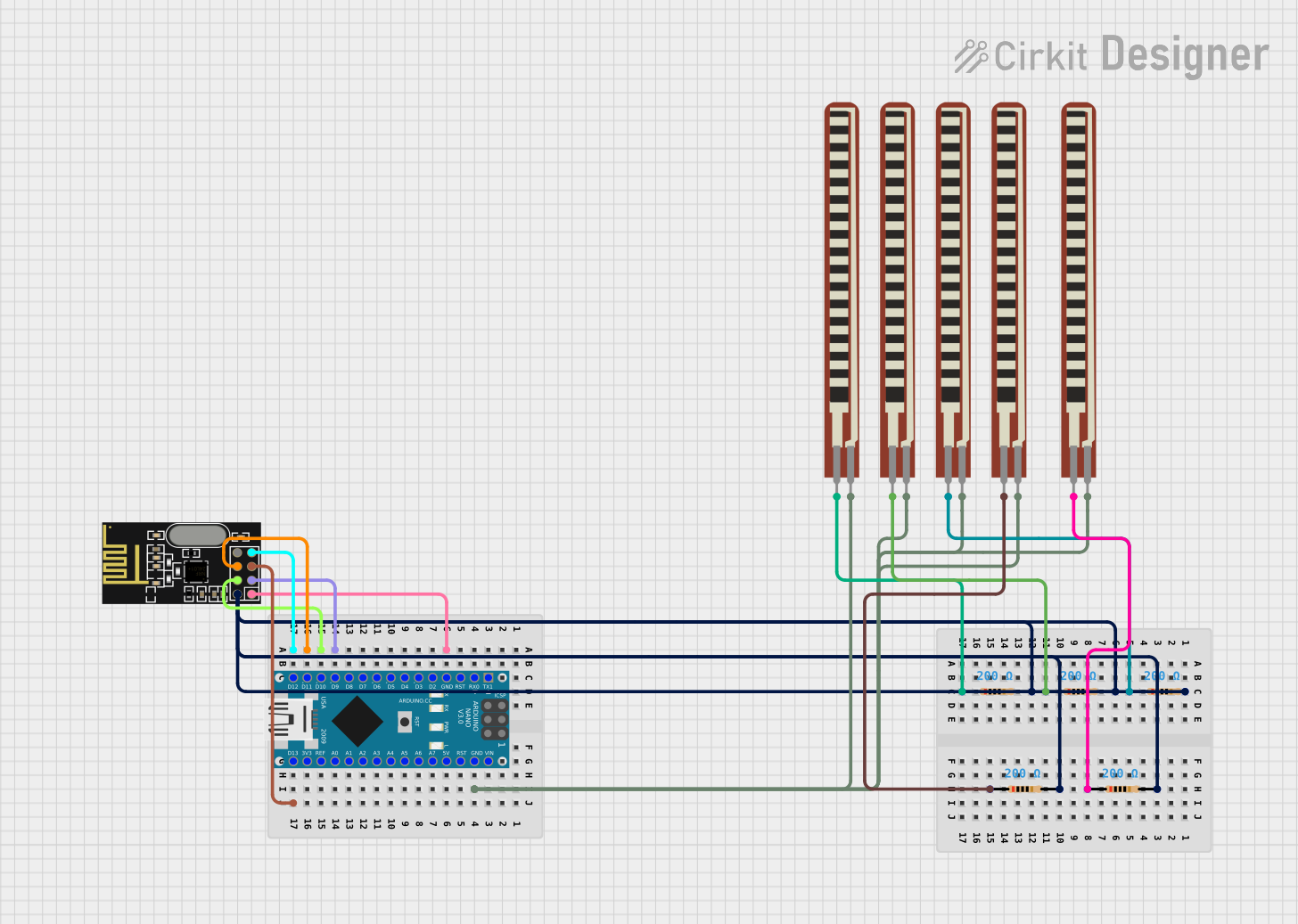 Open Project in Cirkit Designer
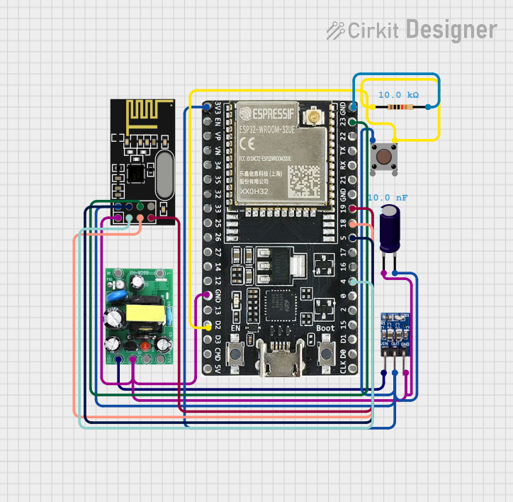 Open Project in Cirkit Designer
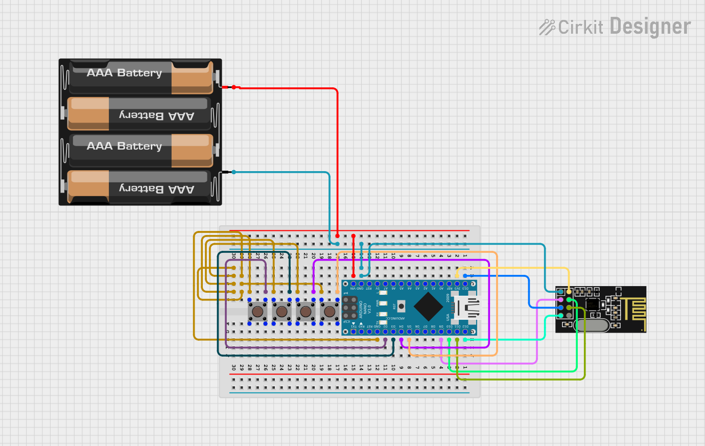 Open Project in Cirkit Designer
Explore Projects Built with RF24G Header
Open Project in Cirkit DesignerOpen Project in Cirkit DesignerOpen Project in Cirkit DesignerOpen Project in Cirkit DesignerCommon Applications and Use Cases
- Wireless communication in IoT devices
- Remote control systems
- Home automation projects
- Wireless sensor networks
- Robotics and telemetry systems
Technical Specifications
The RF24G Header is designed to match the pinout of RF24G wireless modules, ensuring seamless connectivity. Below are the key technical details and pin configuration:
Key Technical Details
- Connector Type: 8-pin header
- Voltage Range: 1.9V to 3.6V (compatible with RF24G module requirements)
- Current Rating: Up to 100mA per pin
- Pin Pitch: 2.54mm (standard breadboard-compatible spacing)
- Operating Temperature: -40°C to 85°C
- Material: Gold-plated pins for corrosion resistance and reliable conductivity
Pin Configuration and Descriptions
The RF24G Header has an 8-pin configuration, as detailed in the table below:
| Pin Number | Pin Name | Description |
|---|---|---|
| 1 | GND | Ground connection |
| 2 | VCC | Power supply (1.9V to 3.6V) |
| 3 | CE | Chip Enable pin for activating the RF24G module |
| 4 | CSN | Chip Select Not pin for SPI communication |
| 5 | SCK | Serial Clock pin for SPI communication |
| 6 | MOSI | Master Out Slave In pin for SPI communication |
| 7 | MISO | Master In Slave Out pin for SPI communication |
| 8 | IRQ | Interrupt Request pin for signaling events |
Usage Instructions
How to Use the RF24G Header in a Circuit
Connect the Header to the RF24G Module:
- Align the RF24G module's pins with the RF24G Header.
- Ensure proper orientation to avoid incorrect connections.
Connect the Header to a Microcontroller:
- Use jumper wires or a PCB to connect the header pins to the corresponding microcontroller pins:
- GND to ground
- VCC to a 3.3V power source
- CE, CSN, SCK, MOSI, and MISO to the respective SPI pins on the microcontroller
- IRQ to an interrupt-capable pin (optional, based on application)
- Use jumper wires or a PCB to connect the header pins to the corresponding microcontroller pins:
Power the Circuit:
- Supply a stable voltage (1.9V to 3.6V) to the VCC pin.
- Ensure the ground (GND) is connected to the common ground of the circuit.
Program the Microcontroller:
- Use appropriate libraries (e.g., RF24 library for Arduino) to configure and communicate with the RF24G module.
Important Considerations and Best Practices
- Voltage Compatibility: Ensure the RF24G module and microcontroller operate within the same voltage range (typically 3.3V).
- Signal Integrity: Use short, high-quality wires to minimize noise and signal degradation.
- Interrupt Pin Usage: If using the IRQ pin, configure the microcontroller to handle interrupts efficiently.
- Static Protection: Handle the RF24G module and header carefully to avoid damage from electrostatic discharge (ESD).
Example Code for Arduino UNO
Below is an example of how to use the RF24G Header with an RF24G module and an Arduino UNO:
#include <SPI.h>
#include <nRF24L01.h>
#include <RF24.h>

// Define RF24G Header pin connections
#define CE_PIN 9   // Connect CE pin of RF24G Header to Arduino pin 9
#define CSN_PIN 10 // Connect CSN pin of RF24G Header to Arduino pin 10

// Create an RF24 object
RF24 radio(CE_PIN, CSN_PIN);

// Define the address for communication
const byte address[6] = "00001";

void setup() {
  Serial.begin(9600); // Initialize serial communication
  radio.begin();      // Initialize the RF24 module
  radio.openWritingPipe(address); // Set the address for transmission
  radio.setPALevel(RF24_PA_LOW);  // Set power level to low
  radio.stopListening();          // Set module to transmit mode
}

void loop() {
  const char text[] = "Hello, RF24G!"; // Message to send
  bool success = radio.write(&text, sizeof(text)); // Send the message

  if (success) {
    Serial.println("Message sent successfully!");
  } else {
    Serial.println("Message failed to send.");
  }

  delay(1000); // Wait 1 second before sending the next message
}
Troubleshooting and FAQs
Common Issues and Solutions
Module Not Responding:
- Cause: Incorrect wiring or loose connections.
- Solution: Double-check all connections between the RF24G Header, RF24G module, and microcontroller.
Communication Failure:
- Cause: Mismatched addresses or incorrect SPI configuration.
- Solution: Ensure the transmitting and receiving modules use the same address and SPI settings.
High Noise or Unstable Operation:
- Cause: Poor power supply or long wires causing signal degradation.
- Solution: Use a decoupling capacitor (e.g., 10µF) across the VCC and GND pins. Keep wires short and well-organized.
IRQ Pin Not Working:
- Cause: Interrupts not configured correctly in the microcontroller.
- Solution: Verify the microcontroller's interrupt settings and ensure the IRQ pin is connected to an interrupt-capable pin.
FAQs
Q: Can I use the RF24G Header with a 5V microcontroller?
A: The RF24G module operates at 3.3V. If using a 5V microcontroller, level shifters or voltage dividers are required for safe operation.
Q: Is the IRQ pin mandatory for operation?
A: No, the IRQ pin is optional. It is used for advanced features like interrupt-driven communication but is not required for basic operation.
Q: Can I use the RF24G Header on a breadboard?
A: Yes, the 2.54mm pin pitch makes it compatible with standard breadboards.