Cirkit Designer Logo
Cirkit Designer
Your all-in-one circuit design IDE
Home / 
Component Documentation

How to Use terminal block 3: Examples, Pinouts, and Specs

Image of terminal block 3
Cirkit Designer LogoDesign with terminal block 3 in Cirkit Designer

Introduction

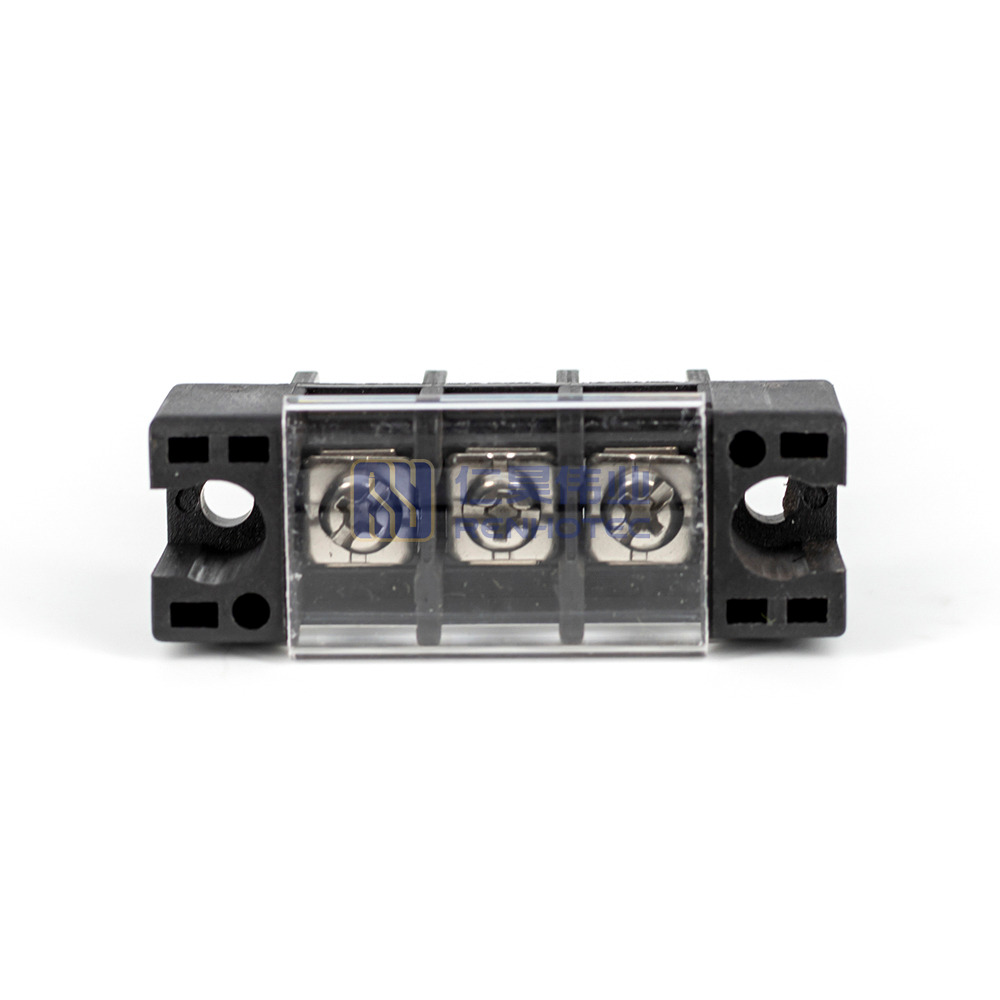
A Terminal Block 3 is an electrical connector that simplifies the process of connecting multiple circuits together. It is designed to consolidate wiring in a secure and organized manner, making it an essential component in various electrical systems. Common applications include industrial control panels, HVAC systems, power supply units, and any scenario where a reliable wire-to-wire or wire-to-device connection is required.

Explore Projects Built with terminal block 3

Use Cirkit Designer to design, explore, and prototype these projects online. Some projects support real-time simulation. Click "Open Project" to start designing instantly!
Battery-Powered Multi-Voltage Supply with Barrel Jack Connectors
Image of Battery Setup: A project utilizing terminal block 3 in a practical application
This circuit consists of multiple 9V batteries connected in series and parallel configurations to provide power to three separate 2.1mm barrel jacks. Each barrel jack receives a different combination of series and parallel battery connections to achieve the desired voltage and current levels.
Cirkit Designer LogoOpen Project in Cirkit Designer
Peltier-Controlled Thermal Management System with SPST Switch
Image of Mini car refrigerator circuit: A project utilizing terminal block 3 in a practical application
This circuit consists of multiple Peltier modules and fans connected in parallel to a digital power supply, with a rocker switch (SPST) controlling the power flow to one of the Peltier modules and multiple fans. The 2.1mm Barrel Jack with Terminal Block serves as the power input connector, and the rocker switch allows for selective enabling or disabling of the connected devices. The circuit is designed to provide cooling or heating through the Peltier modules while the fans assist in heat dissipation or air circulation.
Cirkit Designer LogoOpen Project in Cirkit Designer
Modular Power Distribution System with Multiple SMPS Units and 120V Outlet
Image of Cellion-Tesla: A project utilizing terminal block 3 in a practical application
This circuit is designed to convert 240V AC power to both 12V and 24V DC outputs using multiple SMPS units. Terminal blocks are used to organize and distribute the power, while a 120V outlet provides additional AC power access. The circuit is likely used for powering various electronic devices that require different voltage levels.
Cirkit Designer LogoOpen Project in Cirkit Designer
Battery-Powered Relay Control System with Directional Switch
Image of Skema Lampu D2: A project utilizing terminal block 3 in a practical application
This circuit involves a 12V battery powering a relay system controlled by a directional switch. The relays are connected through terminal blocks and are used to switch between different outputs, indicated by the AdaGator Top components.
Cirkit Designer LogoOpen Project in Cirkit Designer

Explore Projects Built with terminal block 3

Use Cirkit Designer to design, explore, and prototype these projects online. Some projects support real-time simulation. Click "Open Project" to start designing instantly!
Image of Battery Setup: A project utilizing terminal block 3 in a practical application
Battery-Powered Multi-Voltage Supply with Barrel Jack Connectors
This circuit consists of multiple 9V batteries connected in series and parallel configurations to provide power to three separate 2.1mm barrel jacks. Each barrel jack receives a different combination of series and parallel battery connections to achieve the desired voltage and current levels.
Cirkit Designer LogoOpen Project in Cirkit Designer
Image of Mini car refrigerator circuit: A project utilizing terminal block 3 in a practical application
Peltier-Controlled Thermal Management System with SPST Switch
This circuit consists of multiple Peltier modules and fans connected in parallel to a digital power supply, with a rocker switch (SPST) controlling the power flow to one of the Peltier modules and multiple fans. The 2.1mm Barrel Jack with Terminal Block serves as the power input connector, and the rocker switch allows for selective enabling or disabling of the connected devices. The circuit is designed to provide cooling or heating through the Peltier modules while the fans assist in heat dissipation or air circulation.
Cirkit Designer LogoOpen Project in Cirkit Designer
Image of Cellion-Tesla: A project utilizing terminal block 3 in a practical application
Modular Power Distribution System with Multiple SMPS Units and 120V Outlet
This circuit is designed to convert 240V AC power to both 12V and 24V DC outputs using multiple SMPS units. Terminal blocks are used to organize and distribute the power, while a 120V outlet provides additional AC power access. The circuit is likely used for powering various electronic devices that require different voltage levels.
Cirkit Designer LogoOpen Project in Cirkit Designer
Image of Skema Lampu D2: A project utilizing terminal block 3 in a practical application
Battery-Powered Relay Control System with Directional Switch
This circuit involves a 12V battery powering a relay system controlled by a directional switch. The relays are connected through terminal blocks and are used to switch between different outputs, indicated by the AdaGator Top components.
Cirkit Designer LogoOpen Project in Cirkit Designer

Technical Specifications

General Specifications

  • Type: Screw-type terminal block
  • Number of Positions: 3
  • Pitch: Typically 5mm to 10mm (varies by model)
  • Wire Gauge Range: 26-12 AWG (varies by model)
  • Rated Voltage: Up to 600V (varies by model)
  • Rated Current: Up to 15A (varies by model)
  • Operating Temperature Range: -40°C to +105°C (varies by model)
  • Material: Polyamide (PA66), flame-retardant to UL94V-0
  • Terminal Screw: Steel, Zinc plated with a corrosion-resistant finish

Pin Configuration and Descriptions

Pin Number Description
1 Input/Output Terminal 1
2 Input/Output Terminal 2
3 Input/Output Terminal 3

Note: The pin numbers correspond to the terminal positions on the block.

Usage Instructions

Wiring the Terminal Block

  1. Strip the Wires: Remove approximately 5-7mm of insulation from the end of each wire to be connected.
  2. Loosen the Screws: Use a suitable screwdriver to loosen the terminal screws.
  3. Insert the Wires: Insert each stripped wire end into the corresponding terminal hole.
  4. Tighten the Screws: Secure the wires by tightening the terminal screws. Ensure a firm connection without over-tightening, which could damage the wire.

Best Practices

  • Wire Selection: Use wires that match the terminal block's wire gauge range for optimal connection and safety.
  • Torque Specification: Adhere to the manufacturer's torque specifications when tightening terminal screws.
  • Regular Inspection: Periodically check the terminal block for loose connections and signs of wear or damage.
  • Proper Labeling: Clearly label each wire and terminal to facilitate troubleshooting and maintenance.

Troubleshooting and FAQs

Common Issues and Solutions

  • Loose Connections: If a connection is intermittent or fails, check that the terminal screws are properly tightened.
  • Overheating: Overheating can occur due to over-tightening, under-tightening, or using an incorrect wire gauge. Ensure proper installation and wire selection.
  • Corrosion: Protect terminal blocks from moisture and use corrosion-resistant models in harsh environments.

FAQs

Q: Can I use a Terminal Block 3 with an Arduino UNO? A: Yes, a Terminal Block 3 can be used to organize and connect multiple sensors or components to an Arduino UNO.

Q: What is the maximum wire size I can use with a Terminal Block 3? A: The maximum wire size depends on the specific model of the terminal block. Refer to the technical specifications for the wire gauge range.

Q: How do I know if my terminal block is properly installed? A: A properly installed terminal block will have all wires securely fastened without any signs of damage or overheating.

Example Arduino UNO Connection Code

// Define the Arduino pin connected to the terminal block
const int terminalPin = 2;

void setup() {
  // Set the terminal block pin as an output
  pinMode(terminalPin, OUTPUT);
}

void loop() {
  // Send a HIGH signal to the terminal block
  digitalWrite(terminalPin, HIGH);
  delay(1000); // Wait for 1 second
  // Send a LOW signal to the terminal block
  digitalWrite(terminalPin, LOW);
  delay(1000); // Wait for 1 second
}

Note: The above code is a simple example of toggling an output connected to a Terminal Block 3. The actual application will vary based on the connected components and the desired functionality.