Cirkit Designer Logo
Cirkit Designer
Your all-in-one circuit design IDE
Home / 
Component Documentation

How to Use JST XH 7P: Examples, Pinouts, and Specs

Image of JST XH 7P
Cirkit Designer LogoDesign with JST XH 7P in Cirkit Designer

Introduction

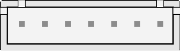
The JST XH 7P is a 7-pin connector from the JST XH series, designed for reliable and compact wire-to-board connections in electronic circuits. Known for its secure locking mechanism and ease of use, this connector is widely used in applications requiring multiple wire connections, such as battery packs, LED strips, and small electronic devices. Its compact design makes it ideal for space-constrained projects while maintaining robust electrical performance.

Explore Projects Built with JST XH 7P

Use Cirkit Designer to design, explore, and prototype these projects online. Some projects support real-time simulation. Click "Open Project" to start designing instantly!
Solar-Powered GSM/GPRS+GPS Tracker with Seeeduino XIAO
Image of SOS System : A project utilizing JST XH 7P in a practical application
This circuit features an Ai Thinker A9G development board for GSM/GPRS and GPS/BDS connectivity, interfaced with a Seeeduino XIAO microcontroller for control and data processing. A solar cell, coupled with a TP4056 charging module, charges a 3.3V battery, which powers the system through a 3.3V regulator ensuring stable operation. The circuit likely serves for remote data communication and location tracking, with the capability to be powered by renewable energy and interfaced with additional sensors or input devices via the Seeeduino XIAO.
Cirkit Designer LogoOpen Project in Cirkit Designer
Arduino UNO Controlled Servo with Joystick and LED Indicator
Image of Joystick + LED + Servo 9G: A project utilizing JST XH 7P in a practical application
This circuit features an Arduino UNO microcontroller connected to a red LED, a micro servo 9G, and a KY-023 Dual Axis Joystick Module. The LED is controlled by digital pin D7 on the Arduino, while the servo is operated by digital pin D6 and is programmed to move based on the joystick's vertical axis (VRy) input. The joystick and servo are powered by the Arduino's 5V output, and all components share a common ground.
Cirkit Designer LogoOpen Project in Cirkit Designer
Arduino UNO Controlled Relay Switching Circuit
Image of StimDemo: A project utilizing JST XH 7P in a practical application
This circuit uses an Arduino UNO to control a 1-Channel Relay. The relay is powered by the Arduino's 5V output and is triggered by a digital signal from pin D7 of the Arduino. A JST PH 2.0 connector is connected to the common (C) and normally open (NO) contacts of the relay, allowing an external device to be switched on and off by the relay.
Cirkit Designer LogoOpen Project in Cirkit Designer
Wireless Joystick-Controlled Interface with Arduino Nano and NRF24L01
Image of Transmitter 11: A project utilizing JST XH 7P in a practical application
This circuit features an Arduino Nano interfaced with a KY-023 Dual Axis Joystick Module for analog input, and an NRF24L01 module for wireless communication. The joystick provides x and y-axis control signals to the Arduino's analog inputs and a switch signal to a digital input, while the NRF24L01 enables the Arduino to communicate with other devices wirelessly. The 2x 18650 batteries supply power to the Arduino, which in turn powers the joystick and the NRF24L01 module.
Cirkit Designer LogoOpen Project in Cirkit Designer

Explore Projects Built with JST XH 7P

Use Cirkit Designer to design, explore, and prototype these projects online. Some projects support real-time simulation. Click "Open Project" to start designing instantly!
Image of SOS System : A project utilizing JST XH 7P in a practical application
Solar-Powered GSM/GPRS+GPS Tracker with Seeeduino XIAO
This circuit features an Ai Thinker A9G development board for GSM/GPRS and GPS/BDS connectivity, interfaced with a Seeeduino XIAO microcontroller for control and data processing. A solar cell, coupled with a TP4056 charging module, charges a 3.3V battery, which powers the system through a 3.3V regulator ensuring stable operation. The circuit likely serves for remote data communication and location tracking, with the capability to be powered by renewable energy and interfaced with additional sensors or input devices via the Seeeduino XIAO.
Cirkit Designer LogoOpen Project in Cirkit Designer
Image of Joystick + LED + Servo 9G: A project utilizing JST XH 7P in a practical application
Arduino UNO Controlled Servo with Joystick and LED Indicator
This circuit features an Arduino UNO microcontroller connected to a red LED, a micro servo 9G, and a KY-023 Dual Axis Joystick Module. The LED is controlled by digital pin D7 on the Arduino, while the servo is operated by digital pin D6 and is programmed to move based on the joystick's vertical axis (VRy) input. The joystick and servo are powered by the Arduino's 5V output, and all components share a common ground.
Cirkit Designer LogoOpen Project in Cirkit Designer
Image of StimDemo: A project utilizing JST XH 7P in a practical application
Arduino UNO Controlled Relay Switching Circuit
This circuit uses an Arduino UNO to control a 1-Channel Relay. The relay is powered by the Arduino's 5V output and is triggered by a digital signal from pin D7 of the Arduino. A JST PH 2.0 connector is connected to the common (C) and normally open (NO) contacts of the relay, allowing an external device to be switched on and off by the relay.
Cirkit Designer LogoOpen Project in Cirkit Designer
Image of Transmitter 11: A project utilizing JST XH 7P in a practical application
Wireless Joystick-Controlled Interface with Arduino Nano and NRF24L01
This circuit features an Arduino Nano interfaced with a KY-023 Dual Axis Joystick Module for analog input, and an NRF24L01 module for wireless communication. The joystick provides x and y-axis control signals to the Arduino's analog inputs and a switch signal to a digital input, while the NRF24L01 enables the Arduino to communicate with other devices wirelessly. The 2x 18650 batteries supply power to the Arduino, which in turn powers the joystick and the NRF24L01 module.
Cirkit Designer LogoOpen Project in Cirkit Designer

Common Applications

  • Battery pack connections in RC vehicles and drones
  • LED strip wiring
  • Power and signal connections in small electronic devices
  • Prototyping and DIY electronics projects

Technical Specifications

The JST XH 7P connector is part of the XH series, which is characterized by a 2.5 mm pitch between pins. Below are the key technical details:

General Specifications

Parameter Value
Number of Pins 7
Pitch (Pin Spacing) 2.5 mm
Rated Voltage 250 V AC/DC
Rated Current 3 A
Contact Resistance ≤ 10 mΩ
Insulation Resistance ≥ 1000 MΩ
Operating Temperature -25°C to +85°C
Connector Type Wire-to-board
Locking Mechanism Friction lock with housing

Pin Configuration

The JST XH 7P connector has seven pins arranged in a single row. The pinout is as follows:

Pin Number Description Typical Use Case
1 VCC (Power Supply) Positive voltage input
2 GND (Ground) Ground connection
3 Signal 1 Data or control signal
4 Signal 2 Data or control signal
5 Signal 3 Data or control signal
6 Signal 4 Data or control signal
7 Signal 5 Data or control signal

Note: The specific pin assignments may vary depending on the application. Always refer to the circuit design or datasheet for proper pin mapping.

Usage Instructions

How to Use the JST XH 7P Connector

  1. Prepare the Wires:

    • Strip approximately 2-3 mm of insulation from the ends of the wires to be connected.
    • Use a crimping tool to attach JST XH-compatible crimp terminals to the stripped wire ends.
  2. Insert the Terminals:

    • Insert the crimped terminals into the connector housing until they click into place.
    • Ensure the terminals are fully seated and aligned with the housing.
  3. Connect to the PCB:

    • Align the JST XH 7P connector with the corresponding header on the PCB.
    • Push the connector into the header until it locks securely.
  4. Verify Connections:

    • Check that all wires are properly connected and that the connector is firmly seated.

Important Considerations

  • Wire Gauge: Use wires with a gauge compatible with the crimp terminals (typically 22-28 AWG).
  • Crimping Tool: Use a dedicated JST crimping tool for reliable connections.
  • Polarity: Ensure correct polarity when connecting power and ground pins to avoid damage to the circuit.
  • Insertion Force: Avoid excessive force when inserting or removing the connector to prevent damage.

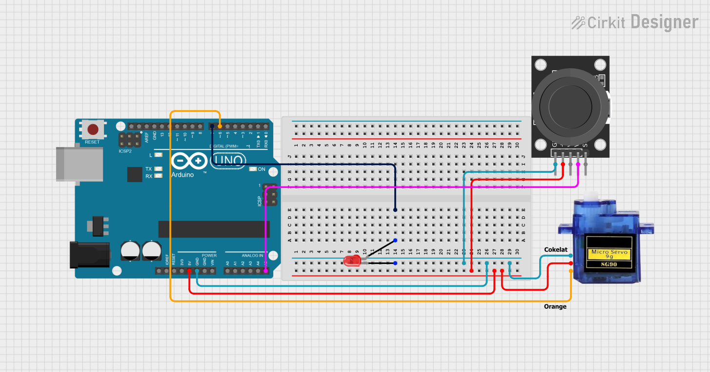
Example: Connecting to an Arduino UNO

The JST XH 7P connector can be used to connect multiple signals or power lines to an Arduino UNO. Below is an example of how to connect the JST XH 7P to an Arduino for controlling an LED strip:

Circuit Setup

  • Pin 1 (VCC) connects to the Arduino's 5V pin.
  • Pin 2 (GND) connects to the Arduino's GND pin.
  • Pins 3-7 connect to digital pins on the Arduino (e.g., D3, D5, D6, D9, D10).

Arduino Code Example

// Example code to control an LED strip connected via JST XH 7P
// Pins 3-7 are used to control individual LEDs or LED segments

const int ledPins[] = {3, 5, 6, 9, 10}; // Define the pins connected to the LEDs

void setup() {
  // Set all LED pins as output
  for (int i = 0; i < 5; i++) {
    pinMode(ledPins[i], OUTPUT);
  }
}

void loop() {
  // Turn LEDs on sequentially
  for (int i = 0; i < 5; i++) {
    digitalWrite(ledPins[i], HIGH); // Turn on LED
    delay(500);                     // Wait for 500 ms
    digitalWrite(ledPins[i], LOW);  // Turn off LED
  }
}

Note: Ensure the LED strip's power requirements match the Arduino's output capabilities.

Troubleshooting and FAQs

Common Issues

  1. Loose Connections:

    • Cause: Terminals not fully inserted into the housing.
    • Solution: Reinsert the terminals and ensure they click into place.
  2. Connector Does Not Fit:

    • Cause: Incorrect header type or misalignment.
    • Solution: Verify the header is compatible with the JST XH 7P and align the connector properly.
  3. Intermittent Signal Loss:

    • Cause: Poor crimping or damaged wires.
    • Solution: Inspect the crimped terminals and wires for damage. Re-crimp if necessary.
  4. Overheating:

    • Cause: Exceeding the rated current of 3 A.
    • Solution: Ensure the current through the connector does not exceed its rating.

FAQs

Q: Can I solder wires directly to the JST XH 7P connector?
A: No, the JST XH 7P is designed for crimped terminals. Soldering may damage the housing or compromise the connection.

Q: What is the maximum wire length I can use with this connector?
A: The maximum wire length depends on the application and signal integrity requirements. For power connections, keep wires as short as possible to minimize voltage drop.

Q: Is the JST XH 7P connector waterproof?
A: No, the JST XH 7P is not waterproof. For outdoor or moisture-prone environments, consider using waterproof connectors.

Q: Can I use this connector for high-frequency signals?
A: The JST XH 7P is suitable for low- to medium-frequency signals. For high-frequency applications, consider connectors designed for impedance matching.