How to Use KY-024: Examples, Pinouts, and Specs
Introduction
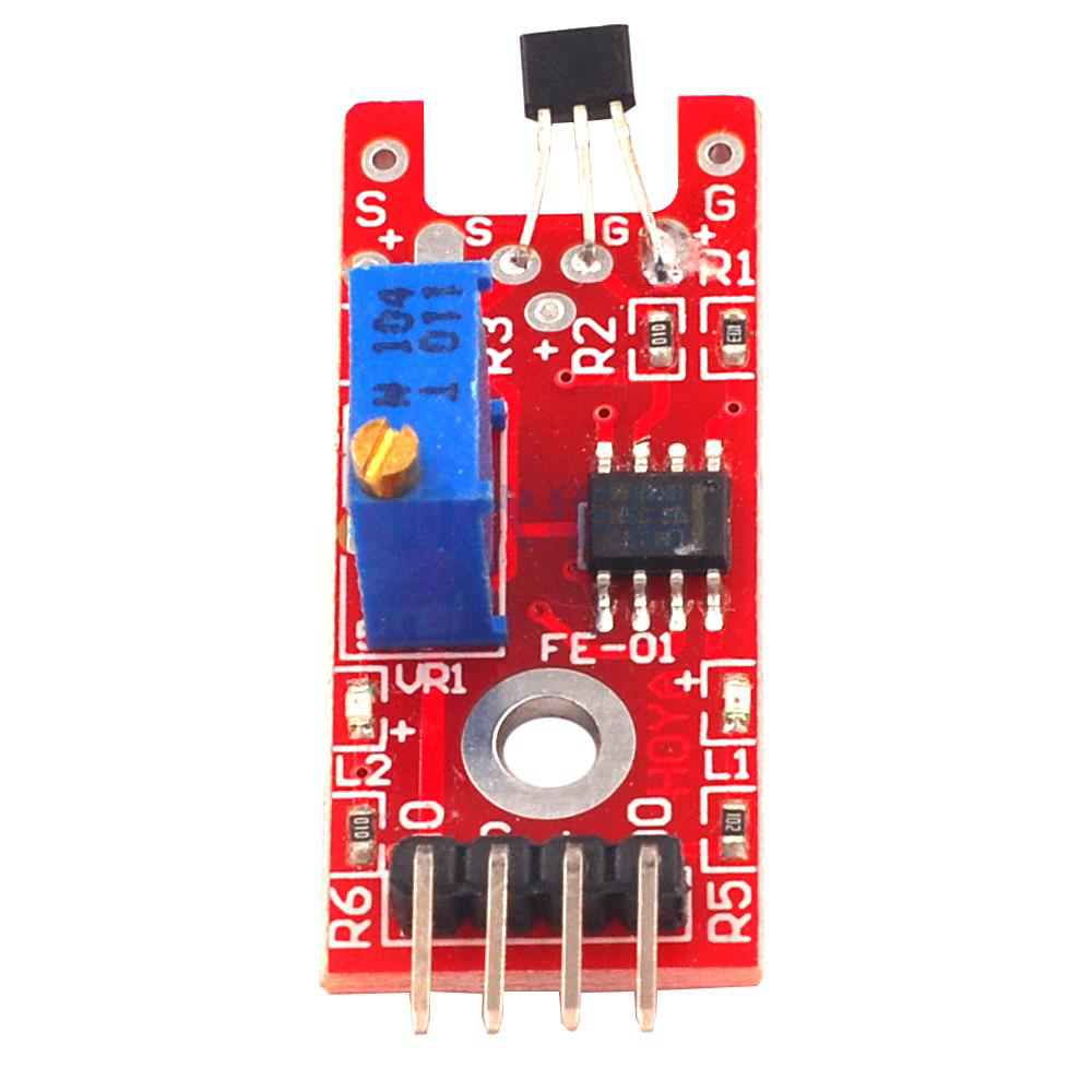
The KY-024 is a linear Hall effect sensor module designed to detect magnetic fields. It outputs an analog voltage that is proportional to the strength of the magnetic field, making it ideal for applications requiring precise magnetic field measurements. Additionally, the module includes a digital output that can be triggered when the magnetic field strength exceeds a user-defined threshold, adjustable via an onboard potentiometer.
Explore Projects Built with KY-024

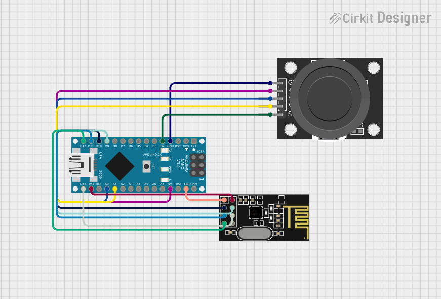

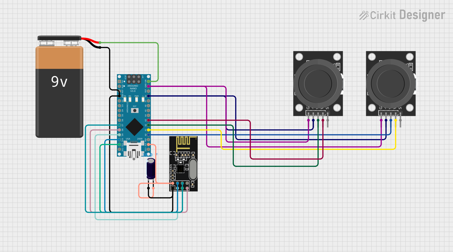
Explore Projects Built with KY-024
Common Applications and Use Cases
- Position sensing in robotics
- Proximity detection
- Magnetic field strength measurement
- Motor speed sensing
- Contactless switches
Technical Specifications
The KY-024 module consists of a linear Hall effect sensor, a comparator, and an onboard potentiometer for sensitivity adjustment. Below are the key technical details:
Key Technical Details
- Operating Voltage: 3.3V to 5V
- Analog Output Voltage: Proportional to magnetic field strength
- Digital Output: High/Low signal based on threshold
- Sensitivity Adjustment: Via onboard potentiometer
- Dimensions: 32mm x 14mm x 8mm
- Operating Temperature: -40°C to 85°C
Pin Configuration and Descriptions
The KY-024 module has 3 pins for interfacing with external circuits. The table below describes each pin:
| Pin | Name | Description |
|---|---|---|
| 1 | VCC | Power supply input (3.3V to 5V) |
| 2 | GND | Ground connection |
| 3 | AOUT | Analog output voltage proportional to the magnetic field strength |
| 4 | DOUT | Digital output signal (High/Low) based on the magnetic field threshold setting |
Usage Instructions
How to Use the KY-024 in a Circuit
- Power the Module: Connect the VCC pin to a 3.3V or 5V power source and the GND pin to ground.
- Read Analog Output: Connect the AOUT pin to an analog input pin on your microcontroller to measure the magnetic field strength.
- Use Digital Output: Connect the DOUT pin to a digital input pin on your microcontroller to detect when the magnetic field exceeds the threshold.
- Adjust Sensitivity: Use the onboard potentiometer to set the desired magnetic field threshold for the digital output.
Important Considerations and Best Practices
- Ensure the module is powered within its operating voltage range (3.3V to 5V) to avoid damage.
- Place the sensor in the desired magnetic field area for accurate readings.
- Avoid placing the module near strong electromagnetic interference sources, as this may affect accuracy.
- Use the analog output for precise measurements and the digital output for simple threshold-based detection.
Example: Connecting KY-024 to an Arduino UNO
Below is an example of how to connect and use the KY-024 with an Arduino UNO:
Circuit Connections
- Connect the KY-024's VCC pin to the Arduino's 5V pin.
- Connect the KY-024's GND pin to the Arduino's GND pin.
- Connect the KY-024's AOUT pin to the Arduino's A0 pin.
- Connect the KY-024's DOUT pin to the Arduino's D2 pin.
Arduino Code Example
// KY-024 Hall Effect Sensor Example Code
// Reads analog and digital outputs from the KY-024 module and displays the results.

const int analogPin = A0;  // Pin connected to AOUT (analog output)
const int digitalPin = 2;  // Pin connected to DOUT (digital output)

void setup() {
  Serial.begin(9600);      // Initialize serial communication
  pinMode(digitalPin, INPUT); // Set DOUT pin as input
}

void loop() {
  int analogValue = analogRead(analogPin); // Read analog value from AOUT
  int digitalValue = digitalRead(digitalPin); // Read digital value from DOUT

  // Print the analog and digital values to the Serial Monitor
  Serial.print("Analog Value: ");
  Serial.print(analogValue);
  Serial.print(" | Digital Value: ");
  Serial.println(digitalValue);

  delay(500); // Wait for 500ms before the next reading
}
Troubleshooting and FAQs
Common Issues and Solutions
No Output from the Module
- Ensure the module is powered correctly (3.3V to 5V).
- Check all connections for loose wires or incorrect pin assignments.
Inaccurate Analog Readings
- Verify that the sensor is placed in the correct magnetic field area.
- Avoid placing the module near strong electromagnetic interference sources.
Digital Output Not Triggering
- Adjust the potentiometer to set the correct threshold for the magnetic field.
- Ensure the magnetic field strength exceeds the set threshold.
Arduino Not Detecting Signals
- Double-check the pin connections between the KY-024 and the Arduino.
- Confirm that the Arduino code matches the connected pins.
FAQs
Q: Can the KY-024 detect both north and south poles of a magnet?
A: Yes, the KY-024 can detect both poles of a magnet. The analog output voltage will vary depending on the strength and polarity of the magnetic field.
Q: How do I know if the digital output is working?
A: The onboard LED will light up when the digital output is triggered, indicating that the magnetic field strength has exceeded the threshold.
Q: Can I use the KY-024 with a 3.3V microcontroller?
A: Yes, the KY-024 is compatible with 3.3V microcontrollers, but ensure the power supply voltage matches the microcontroller's requirements.
Q: What is the range of the analog output voltage?
A: The analog output voltage typically ranges from 0V to the supply voltage (3.3V or 5V), depending on the magnetic field strength.
By following this documentation, you can effectively integrate the KY-024 Hall effect sensor module into your projects for reliable magnetic field detection and measurement.