How to Use Arduino Nano RP2040 Connect: Examples, Pinouts, and Specs
Introduction
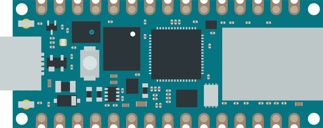
The Arduino Nano RP2040 Connect is a microcontroller board based on the Raspberry Pi RP2040 microcontroller. It is a compact and feature-rich development platform that is part of the Arduino Nano family. With built-in WiFi and Bluetooth connectivity, it is an ideal choice for Internet of Things (IoT) projects, wireless applications, and smart devices. The board's small form factor and extensive GPIO capabilities make it suitable for prototyping and embedding into final products.
Explore Projects Built with Arduino Nano RP2040 Connect
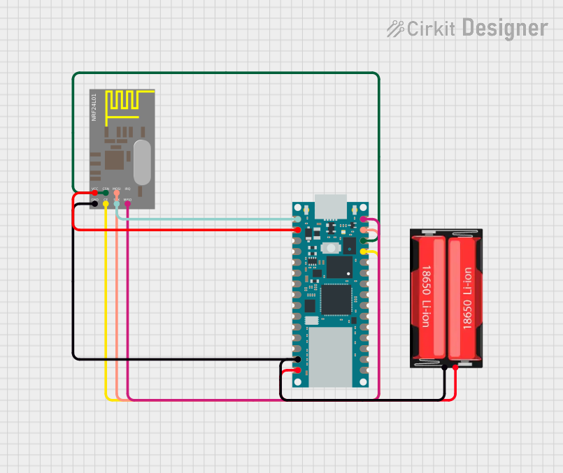
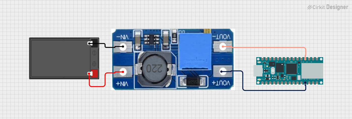
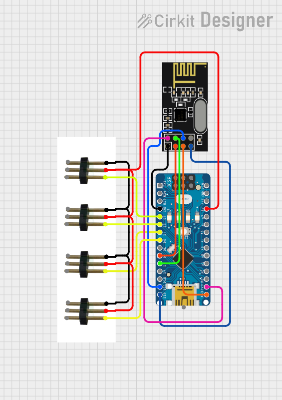
Explore Projects Built with Arduino Nano RP2040 Connect
Common Applications and Use Cases
- IoT devices
- Wearable technology
- Smart home applications
- Wireless sensor networks
- Educational projects and learning platforms
- Prototyping for embedded systems
Technical Specifications
Key Technical Details
- Microcontroller: Raspberry Pi RP2040
- Operating Voltage: 3.3V
- Input Voltage (VIN): 5V-21V
- Digital I/O Pins: 22
- Analog Input Pins: 8
- PWM Pins: 20
- UART, SPI, I2C Interfaces
- Clock Speed: 133 MHz
- Flash Memory: 16MB
- SRAM: 264KB
- Built-in WiFi: 2.4 GHz 802.11 b/g/n
- Built-in Bluetooth: BLE 5.0
Pin Configuration and Descriptions
| Pin Number | Function | Description |
|---|---|---|
| 1 | D2 | Digital I/O, Interrupt, PWM |
| 2 | D3 | Digital I/O, Interrupt, PWM, DAC |
| ... | ... | ... |
| 29 | A6 | Analog Input |
| 30 | A7 | Analog Input |
| ... | ... | ... |
| 39 | VIN | Input voltage to the board |
| 40 | GND | Ground |
| ... | ... | ... |
| 43 | 3V3 | 3.3V output |
| 44 | RST | Reset pin |
Note: This is a partial representation of the pin configuration. Refer to the official datasheet for the complete pinout.
Usage Instructions
How to Use the Component in a Circuit
Powering the Board:
- Connect the VIN pin to a 5V-21V power source, or plug in a USB cable to the board's USB port.
Connecting to a Computer:
- Use a USB cable to connect the board to a computer for programming or serial communication.
Interfacing with Sensors and Actuators:
- Utilize the digital and analog pins to connect sensors and actuators. Ensure that the connected devices are compatible with the board's operating voltage.
Wireless Connectivity:
- Use the onboard WiFi and Bluetooth for wireless communication. Set up the network credentials and pair devices as needed.
Important Considerations and Best Practices
- Always ensure that the power supply is within the specified range to prevent damage.
- When interfacing with other components, consider the current ratings of the I/O pins.
- Use proper decoupling capacitors close to the board's power pins to minimize noise.
- Avoid exposing the board to static electricity or physical stress.
- Keep the firmware updated to the latest version for optimal performance and security.
Troubleshooting and FAQs
Common Issues Users Might Face
Board not recognized by the computer:
- Check the USB cable and connections.
- Ensure the correct drivers are installed.
WiFi or Bluetooth not functioning:
- Verify the antenna is not obstructed.
- Check the network settings and credentials.
Inconsistent behavior or crashes:
- Ensure the power supply is stable and within the specified range.
- Check for any shorts or incorrect connections in the circuit.
Solutions and Tips for Troubleshooting
- Always start with a simple blink sketch to ensure the board is functioning correctly.
- Use serial print statements to debug and track down issues in your code.
- Consult the Arduino forums and community for support and advice.
Example Code for Arduino UNO
// This example code is designed to quickly deploy a WiFi connection.
#include <WiFiNINA.h>

char ssid[] = "yourNetwork"; // your network SSID (name)
char pass[] = "secretPassword"; // your network password

int status = WL_IDLE_STATUS;

void setup() {
  // Initialize serial and wait for the port to open:
  Serial.begin(9600);
  while (!Serial) {
    ; // wait for serial port to connect.
  }

  // Attempt to connect to WiFi network:
  while (status != WL_CONNECTED) {
    Serial.print("Attempting to connect to SSID: ");
    Serial.println(ssid);
    // Connect to WPA/WPA2 network:
    status = WiFi.begin(ssid, pass);

    // Wait 10 seconds for connection:
    delay(10000);
  }

  // Once connected, print the IP address:
  Serial.print("Connected to ");
  Serial.println(ssid);
  Serial.print("IP address: ");
  Serial.println(WiFi.localIP());
}

void loop() {
  // Maintain WiFi connection:
  status = WiFi.status();
  if ( status != WL_CONNECTED) {
    while (status != WL_CONNECTED) {
      // Connect to WPA/WPA2 network:
      status = WiFi.begin(ssid, pass);
      // Wait 10 seconds for connection:
      delay(10000);
    }
    Serial.println("Reconnected to WiFi");
  }
}
Note: Replace yourNetwork and secretPassword with your actual WiFi network name and password.
This documentation provides an overview of the Arduino Nano RP2040 Connect board. For more detailed information, refer to the official Arduino documentation and datasheets.