
How to Use STM811: Examples, Pinouts, and Specs
 Design with STM811 in Cirkit Designer
Introduction
The STM811 is a microprocessor supervisory circuit designed to ensure reliable operation of microcontrollers and other digital systems. It monitors the supply voltage and generates a reset signal when the voltage drops below a predefined threshold. This functionality is critical for preventing erratic behavior during power-up, power-down, or brownout conditions. The STM811 is compact, efficient, and widely used in embedded systems to enhance system stability and reliability.
Explore Projects Built with STM811
 Open Project in Cirkit Designer
 Open Project in Cirkit Designer
 Open Project in Cirkit Designer
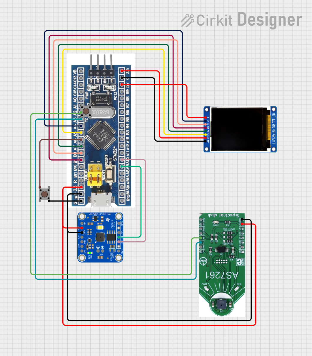 Open Project in Cirkit Designer
Explore Projects Built with STM811
Open Project in Cirkit DesignerOpen Project in Cirkit DesignerOpen Project in Cirkit DesignerOpen Project in Cirkit DesignerCommon Applications and Use Cases
- Power-on reset and brownout protection for microcontrollers
- Embedded systems requiring reliable startup and shutdown
- Battery-powered devices to prevent malfunction during low battery conditions
- Industrial control systems and IoT devices
- Consumer electronics and automotive applications
Technical Specifications
Key Technical Details
- Operating Voltage Range: 1.0V to 5.5V
- Reset Threshold Voltage: Configurable (varies by model, e.g., 2.63V, 2.93V, etc.)
- Reset Output: Active-low (push-pull or open-drain, depending on variant)
- Reset Pulse Width: Minimum 140ms (typical)
- Operating Temperature Range: -40°C to +85°C
- Low Supply Current: 3µA (typical)
- Package Options: SOT23-3, SOT23-5
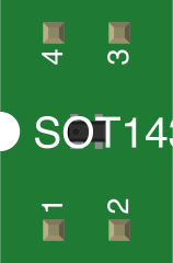
Pin Configuration and Descriptions
SOT23-3 Package
| Pin Number | Pin Name | Description |
|---|---|---|
| 1 | GND | Ground |
| 2 | RESET | Reset output (active-low) |
| 3 | VCC | Supply voltage input |
SOT23-5 Package
| Pin Number | Pin Name | Description |
|---|---|---|
| 1 | GND | Ground |
| 2 | RESET | Reset output (active-low) |
| 3 | VCC | Supply voltage input |
| 4 | MR | Manual reset input (active-low) |
| 5 | NC | No connection (leave unconnected) |
Usage Instructions
How to Use the STM811 in a Circuit
- Power Supply Connection: Connect the VCC pin to the system's supply voltage (1.0V to 5.5V) and the GND pin to the ground.
- Reset Output: Connect the RESET pin to the reset input of the microcontroller or digital system. Ensure the microcontroller's reset pin is configured to accept an active-low signal.
- Manual Reset (SOT23-5 only): If using the SOT23-5 package, connect a push-button switch between the MR pin and GND to allow manual reset functionality. Pull the MR pin high using a resistor (e.g., 10kΩ) to prevent false triggering.
- Decoupling Capacitor: Place a 0.1µF ceramic capacitor close to the VCC pin to stabilize the supply voltage and reduce noise.
Important Considerations and Best Practices
- Ensure the reset threshold voltage of the STM811 matches the operating voltage requirements of your microcontroller or system.
- For systems with noisy power supplies, consider adding additional filtering capacitors to improve stability.
- Avoid leaving unused pins (e.g., MR or NC) floating. Follow the manufacturer's recommendations for proper handling.
- Verify the reset pulse width (140ms typical) is sufficient for your microcontroller's startup requirements.
Example: Connecting STM811 to an Arduino UNO
The STM811 can be used to provide reliable reset functionality for an Arduino UNO. Below is an example circuit and Arduino code:
Circuit Diagram
- Connect the STM811's VCC pin to the Arduino's 5V pin.
- Connect the GND pin to the Arduino's GND pin.
- Connect the RESET pin to the Arduino's RESET pin.
Arduino Code Example
// Example code to demonstrate the STM811 reset functionality
// This code toggles an LED to indicate normal operation. If the STM811
// triggers a reset, the Arduino will restart and the LED will blink again.

const int ledPin = 13; // Built-in LED pin on Arduino UNO

void setup() {
  pinMode(ledPin, OUTPUT); // Set LED pin as output
}

void loop() {
  digitalWrite(ledPin, HIGH); // Turn LED on
  delay(500);                 // Wait for 500ms
  digitalWrite(ledPin, LOW);  // Turn LED off
  delay(500);                 // Wait for 500ms
}
Troubleshooting and FAQs
Common Issues and Solutions
Reset Signal Not Triggering:
- Verify the supply voltage is within the operating range of the STM811.
- Check the connections to the RESET pin and ensure it is properly connected to the microcontroller's reset input.
False Resets:
- Ensure the VCC pin is properly decoupled with a 0.1µF capacitor to reduce noise.
- If using the MR pin, confirm it is pulled high with a resistor when not in use.
Microcontroller Does Not Start After Reset:
- Verify the reset pulse width (140ms typical) is sufficient for the microcontroller's startup time.
- Check for proper connections between the STM811 and the microcontroller.
FAQs
Q1: Can the STM811 be used with 3.3V systems?
A1: Yes, the STM811 supports operating voltages as low as 1.0V and is compatible with 3.3V systems. Ensure the reset threshold voltage matches your system's requirements.
Q2: What is the difference between push-pull and open-drain RESET outputs?
A2: Push-pull outputs actively drive both high and low states, while open-drain outputs require an external pull-up resistor to drive the high state. Check your system's requirements before selecting the STM811 variant.
Q3: Can I leave the MR pin unconnected in the SOT23-5 package?
A3: No, the MR pin should be pulled high with a resistor (e.g., 10kΩ) if not used to prevent false resets.
Q4: How do I select the correct reset threshold voltage?
A4: Choose a reset threshold voltage slightly below your system's nominal operating voltage to ensure reliable operation during voltage fluctuations. Refer to the STM811 datasheet for available threshold options.