
How to Use Billie the Blue LED: Examples, Pinouts, and Specs

 Design with Billie the Blue LED in Cirkit Designer
Introduction
Billie the Blue LED is a light-emitting diode (LED) that emits a vibrant blue light when an electric current flows through it. This component is widely used in various applications, including status indicators, decorative lighting, and electronic projects requiring a visually striking blue light. Its compact size, low power consumption, and long lifespan make it an essential component for hobbyists and professionals alike.
Common applications for Billie the Blue LED include:
- Power and status indicators in electronic devices
- Decorative lighting in DIY projects
- Backlighting for displays and panels
- Educational and prototyping purposes in electronics
Explore Projects Built with Billie the Blue LED
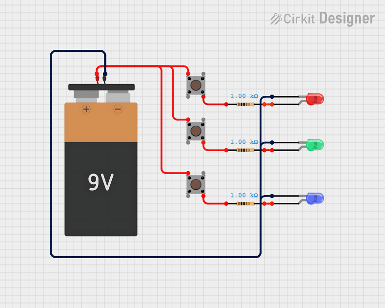 Open Project in Cirkit Designer
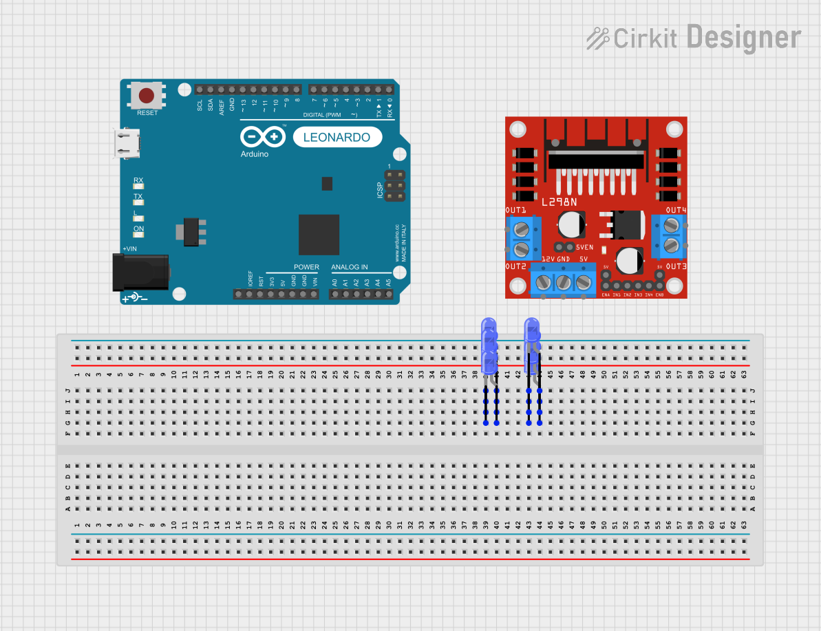 Open Project in Cirkit Designer
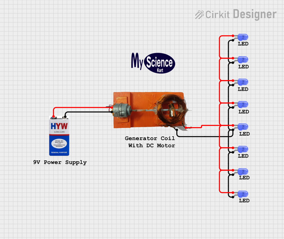 Open Project in Cirkit Designer
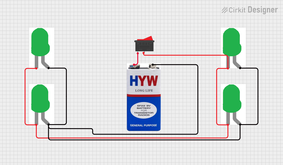 Open Project in Cirkit Designer
Explore Projects Built with Billie the Blue LED
Open Project in Cirkit DesignerOpen Project in Cirkit DesignerOpen Project in Cirkit DesignerOpen Project in Cirkit DesignerTechnical Specifications
Below are the key technical details for Billie the Blue LED:
| Parameter | Value |
|---|---|
| Forward Voltage (Vf) | 2.8V to 3.4V |
| Forward Current (If) | 20mA (typical), 30mA (max) |
| Luminous Intensity | 2000 to 3000 mcd |
| Wavelength | 465nm to 475nm (blue light) |
| Viewing Angle | 20° to 30° |
| Reverse Voltage (Vr) | 5V (maximum) |
| Power Dissipation | 100mW (maximum) |
| Operating Temperature | -40°C to +85°C |
| Package Type | 5mm round (commonly used) |
Pin Configuration
Billie the Blue LED has two pins: the anode (positive) and the cathode (negative). The table below describes the pin configuration:
| Pin | Description |
|---|---|
| Anode (+) | Connects to the positive terminal of the power supply |
| Cathode (-) | Connects to the negative terminal or ground |
Note: The longer leg of the LED is the anode, while the shorter leg is the cathode. If the legs are trimmed, the flat edge on the LED casing indicates the cathode.
Usage Instructions
How to Use Billie the Blue LED in a Circuit
Determine the Resistor Value: To prevent damage to the LED, always use a current-limiting resistor in series with it. The resistor value can be calculated using Ohm's Law: [ R = \frac{V_{supply} - V_f}{I_f} ] Where:
- ( V_{supply} ) is the supply voltage
- ( V_f ) is the forward voltage of the LED (typically 3.0V)
- ( I_f ) is the desired forward current (typically 20mA or 0.02A)
For example, if ( V_{supply} = 5V ): [ R = \frac{5V - 3.0V}{0.02A} = 100\Omega ]
Connect the LED:
- Connect the anode (longer leg) to the positive terminal of the power supply through the resistor.
- Connect the cathode (shorter leg) to the ground.
Power the Circuit: Apply the appropriate voltage to the circuit. The LED will emit blue light when powered correctly.
Important Considerations and Best Practices
- Polarity Matters: Ensure the anode and cathode are connected correctly. Reversing the polarity may damage the LED.
- Use a Resistor: Never connect the LED directly to a power source without a resistor, as this can cause excessive current flow and permanently damage the LED.
- Avoid Overheating: Operate the LED within its specified current and voltage limits to prevent overheating and ensure a long lifespan.
- Test Before Soldering: If using the LED in a permanent circuit, test it on a breadboard first to confirm proper operation.
Example: Connecting Billie the Blue LED to an Arduino UNO
Below is an example of how to connect Billie the Blue LED to an Arduino UNO and make it blink:
Circuit Setup
- Connect the anode of the LED to digital pin 9 on the Arduino through a 220Ω resistor.
- Connect the cathode of the LED to the Arduino's GND pin.
Arduino Code
// Billie the Blue LED Blink Example
// This code makes the LED connected to pin 9 blink on and off every second.

const int ledPin = 9; // Pin connected to the LED

void setup() {
  pinMode(ledPin, OUTPUT); // Set pin 9 as an output
}

void loop() {
  digitalWrite(ledPin, HIGH); // Turn the LED on
  delay(1000);               // Wait for 1 second
  digitalWrite(ledPin, LOW);  // Turn the LED off
  delay(1000);               // Wait for 1 second
}
Note: The 220Ω resistor is used to limit the current to a safe level for both the LED and the Arduino.
Troubleshooting and FAQs
Common Issues
The LED Does Not Light Up:
- Cause: Incorrect polarity.
- Solution: Ensure the anode is connected to the positive terminal and the cathode to ground.
- Cause: No current-limiting resistor or incorrect resistor value.
- Solution: Use a resistor with the correct value (e.g., 100Ω to 220Ω for a 5V supply).
- Cause: Incorrect polarity.
The LED is Dim:
- Cause: Insufficient current.
- Solution: Check the resistor value and ensure it allows enough current (e.g., 20mA).
- Cause: Low supply voltage.
- Solution: Verify that the supply voltage meets the LED's forward voltage requirement.
- Cause: Insufficient current.
The LED Burned Out:
- Cause: Excessive current or voltage.
- Solution: Always use a current-limiting resistor and operate within the specified voltage and current limits.
- Cause: Excessive current or voltage.
FAQs
Can I use Billie the Blue LED with a 3.3V power supply? Yes, but ensure the resistor value is adjusted to limit the current to 20mA.
What happens if I connect the LED without a resistor? The LED may draw excessive current, causing it to overheat and fail.
Can I use multiple LEDs in a circuit? Yes, but each LED should have its own current-limiting resistor, or you can connect them in series/parallel with appropriate calculations.
By following these guidelines, Billie the Blue LED will provide reliable and vibrant blue light for your projects!