Cirkit Designer Logo
Cirkit Designer
Your all-in-one circuit design IDE
Home / 
Component Documentation

How to Use BW16: Examples, Pinouts, and Specs

Image of BW16
Cirkit Designer LogoDesign with BW16 in Cirkit Designer

Introduction

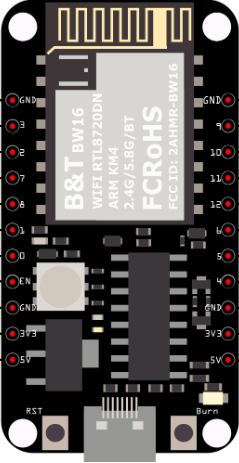
The BW16, manufactured by Realtek with the part ID RTL8720DN, is a versatile Wi-Fi and Bluetooth module designed for Internet of Things (IoT) applications. This module integrates a high-performance microcontroller, making it an ideal choice for projects requiring wireless connectivity. The BW16 supports both Wi-Fi and Bluetooth communication, enabling seamless integration into a wide range of applications, including smart home devices, wearable technology, and industrial automation.

Explore Projects Built with BW16

Use Cirkit Designer to design, explore, and prototype these projects online. Some projects support real-time simulation. Click "Open Project" to start designing instantly!
ESP32 and BW16-Kit-1 Microcontroller Communication Hub with Buzzer Notification
Image of BiJiQ Wi-Fi To.oL: A project utilizing BW16 in a practical application
This circuit features two ESP32 microcontrollers configured to communicate with each other via serial connection, as indicated by the cross-connection of their TX2 and RX2 pins. A BW16-Kit-1 microcontroller is also included, interfacing with one of the ESP32s through pins D26 and D27. Power is supplied to the microcontrollers through a step-down buck converter connected to a 5V Type C DC socket, and a buzzer is driven by one of the ESP32s, potentially for audio signaling purposes.
Cirkit Designer LogoOpen Project in Cirkit Designer
Arduino UNO Controlled RGB LED Matrix with Bluetooth Connectivity and Audio Output
Image of the bell : A project utilizing BW16 in a practical application
This is an interactive display and communication circuit. It uses an Arduino UNO to drive multiple WS2812 RGB LED matrices for visual output, interfaces with a DS3231 RTC for time-related functions, and communicates wirelessly via an HC-05 Bluetooth module. Additionally, it features audio output capabilities through a speaker connected to a PAM8403 audio amplifier.
Cirkit Designer LogoOpen Project in Cirkit Designer
ESP32-WROOM-32UE Wi-Fi Controlled Robotic Car with OLED Display and RGB LED
Image of mkrl bot: A project utilizing BW16 in a practical application
This circuit is a WiFi-controlled robotic system powered by an ESP32 microcontroller. It features an OLED display for status messages, an RGB LED for visual feedback, and dual hobby gearmotors driven by an L9110 motor driver for movement. The system is powered by a 4 x AAA battery pack regulated to 5V using a 7805 voltage regulator.
Cirkit Designer LogoOpen Project in Cirkit Designer
ESP32-CAM Smart Security System with PIR Sensor and BMP280, Battery-Powered and Wi-Fi Controlled
Image of ESP 32: A project utilizing BW16 in a practical application
This circuit is a wireless surveillance system using an ESP32-CAM module, a PIR motion sensor, and a BMP280 sensor. The ESP32-CAM captures images and sends them via Telegram when motion is detected by the PIR sensor, while the BMP280 provides environmental data. The system is powered by a 3.7V battery, regulated to 5V using an LM340T5 7805 voltage regulator, and includes a TP4056 for battery charging.
Cirkit Designer LogoOpen Project in Cirkit Designer

Explore Projects Built with BW16

Use Cirkit Designer to design, explore, and prototype these projects online. Some projects support real-time simulation. Click "Open Project" to start designing instantly!
Image of BiJiQ Wi-Fi To.oL: A project utilizing BW16 in a practical application
ESP32 and BW16-Kit-1 Microcontroller Communication Hub with Buzzer Notification
This circuit features two ESP32 microcontrollers configured to communicate with each other via serial connection, as indicated by the cross-connection of their TX2 and RX2 pins. A BW16-Kit-1 microcontroller is also included, interfacing with one of the ESP32s through pins D26 and D27. Power is supplied to the microcontrollers through a step-down buck converter connected to a 5V Type C DC socket, and a buzzer is driven by one of the ESP32s, potentially for audio signaling purposes.
Cirkit Designer LogoOpen Project in Cirkit Designer
Image of the bell : A project utilizing BW16 in a practical application
Arduino UNO Controlled RGB LED Matrix with Bluetooth Connectivity and Audio Output
This is an interactive display and communication circuit. It uses an Arduino UNO to drive multiple WS2812 RGB LED matrices for visual output, interfaces with a DS3231 RTC for time-related functions, and communicates wirelessly via an HC-05 Bluetooth module. Additionally, it features audio output capabilities through a speaker connected to a PAM8403 audio amplifier.
Cirkit Designer LogoOpen Project in Cirkit Designer
Image of mkrl bot: A project utilizing BW16 in a practical application
ESP32-WROOM-32UE Wi-Fi Controlled Robotic Car with OLED Display and RGB LED
This circuit is a WiFi-controlled robotic system powered by an ESP32 microcontroller. It features an OLED display for status messages, an RGB LED for visual feedback, and dual hobby gearmotors driven by an L9110 motor driver for movement. The system is powered by a 4 x AAA battery pack regulated to 5V using a 7805 voltage regulator.
Cirkit Designer LogoOpen Project in Cirkit Designer
Image of ESP 32: A project utilizing BW16 in a practical application
ESP32-CAM Smart Security System with PIR Sensor and BMP280, Battery-Powered and Wi-Fi Controlled
This circuit is a wireless surveillance system using an ESP32-CAM module, a PIR motion sensor, and a BMP280 sensor. The ESP32-CAM captures images and sends them via Telegram when motion is detected by the PIR sensor, while the BMP280 provides environmental data. The system is powered by a 3.7V battery, regulated to 5V using an LM340T5 7805 voltage regulator, and includes a TP4056 for battery charging.
Cirkit Designer LogoOpen Project in Cirkit Designer

Technical Specifications

Key Technical Details

Parameter Value
Manufacturer Realtek
Part ID RTL8720DN
Wi-Fi Standard 802.11 b/g/n
Bluetooth Standard Bluetooth 5.0
Operating Voltage 3.3V
Operating Current 80mA (Wi-Fi), 30mA (Bluetooth)
Flash Memory 2MB
SRAM 512KB
Operating Temperature -40°C to 85°C
Dimensions 18mm x 20mm x 3mm

Pin Configuration and Descriptions

Pin Number Pin Name Description
1 VCC Power supply (3.3V)
2 GND Ground
3 TXD UART Transmit Data
4 RXD UART Receive Data
5 GPIO0 General Purpose Input/Output 0
6 GPIO1 General Purpose Input/Output 1
7 GPIO2 General Purpose Input/Output 2
8 GPIO3 General Purpose Input/Output 3
9 ADC Analog to Digital Converter Input
10 PWM Pulse Width Modulation Output
11 RST Reset
12 EN Enable

Usage Instructions

How to Use the BW16 in a Circuit

  1. Power Supply: Connect the VCC pin to a 3.3V power source and the GND pin to the ground.
  2. UART Communication: Connect the TXD pin to the RX pin of your microcontroller and the RXD pin to the TX pin of your microcontroller for serial communication.
  3. GPIO Pins: Use the GPIO pins for general-purpose input/output operations. These can be configured as either input or output depending on your application.
  4. ADC: Connect an analog sensor to the ADC pin to read analog values.
  5. PWM: Use the PWM pin to control devices like LEDs or motors with pulse width modulation.
  6. Reset and Enable: Connect the RST pin to a push button for manual reset and the EN pin to enable the module.

Important Considerations and Best Practices

  • Power Supply: Ensure a stable 3.3V power supply to avoid damaging the module.
  • Antenna Placement: For optimal wireless performance, place the module away from metal objects and other sources of interference.
  • Firmware Updates: Regularly check for firmware updates from Realtek to ensure the module operates with the latest features and security patches.
  • Heat Management: If operating in high-temperature environments, consider adding heat sinks or other cooling mechanisms.

Example Code for Arduino UNO

Below is an example code to connect the BW16 module to an Arduino UNO for basic Wi-Fi communication.

#include <SoftwareSerial.h>

SoftwareSerial bw16(10, 11); // RX, TX

void setup() {
  Serial.begin(9600);        // Initialize serial communication at 9600 baud
  bw16.begin(9600);          // Initialize BW16 serial communication at 9600 baud
  Serial.println("BW16 Wi-Fi Module Test");
  bw16.println("AT");        // Send AT command to BW16
}

void loop() {
  if (bw16.available()) {    // Check if BW16 has sent data
    String response = bw16.readString();
    Serial.println(response); // Print the response from BW16 to Serial Monitor
  }

  if (Serial.available()) {  // Check if user has sent data from Serial Monitor
    String command = Serial.readString();
    bw16.println(command);   // Send the command to BW16
  }
}

Troubleshooting and FAQs

Common Issues and Solutions

  1. Module Not Responding:

    • Solution: Check the power supply and ensure it is stable at 3.3V. Verify the connections, especially the TX and RX pins.
  2. Wi-Fi Connection Issues:

    • Solution: Ensure the correct SSID and password are used. Check for interference from other wireless devices.
  3. Bluetooth Pairing Problems:

    • Solution: Make sure the module is in pairing mode. Verify that the device you are pairing with supports Bluetooth 5.0.
  4. Overheating:

    • Solution: Ensure proper ventilation and consider adding a heat sink if the module operates in a high-temperature environment.

FAQs

  1. Can the BW16 operate on 5V?

    • No, the BW16 operates on a 3.3V power supply. Using 5V can damage the module.
  2. How do I update the firmware?

    • Firmware updates can be obtained from Realtek's official website. Follow the provided instructions for updating the firmware.
  3. Can I use the BW16 for both Wi-Fi and Bluetooth simultaneously?

    • Yes, the BW16 supports simultaneous Wi-Fi and Bluetooth operation, making it ideal for complex IoT applications.

By following this documentation, users can effectively integrate the BW16 module into their projects, ensuring reliable and efficient wireless communication.