
How to Use SCR MCR100-6 back: Examples, Pinouts, and Specs
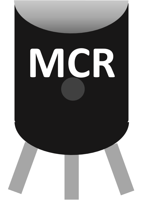
 Design with SCR MCR100-6 back in Cirkit Designer
Introduction
The SCR MCR100-6 is a silicon-controlled rectifier (SCR) designed for controlling power in a wide range of applications. This semiconductor device is capable of handling high voltage and current, making it ideal for use in motor control, lighting systems, heating elements, and other power management applications. The SCR is triggered by a gate signal, allowing it to switch on and off efficiently, which is particularly useful in AC and DC circuits requiring precise control.
Common applications of the SCR MCR100-6 include:
- Motor speed control
- Light dimming circuits
- Temperature regulation in heating systems
- Overvoltage protection
- Phase control in AC circuits
Explore Projects Built with SCR MCR100-6 back
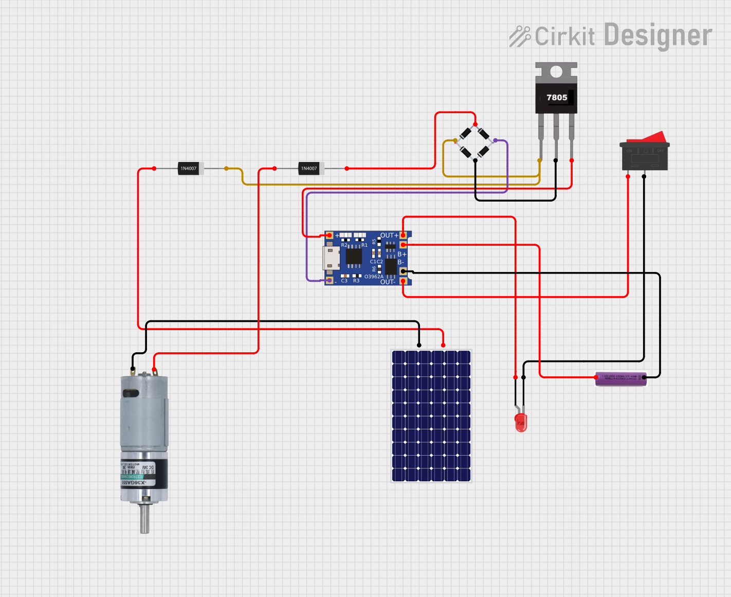 Open Project in Cirkit Designer
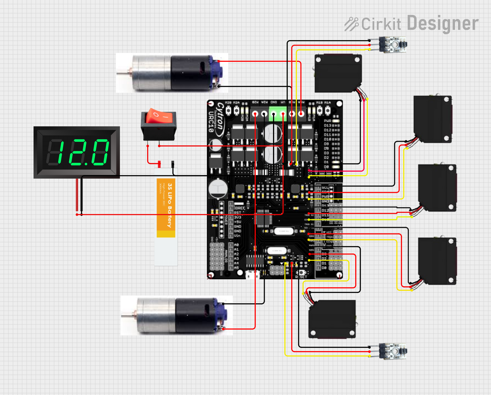 Open Project in Cirkit Designer
 Open Project in Cirkit Designer
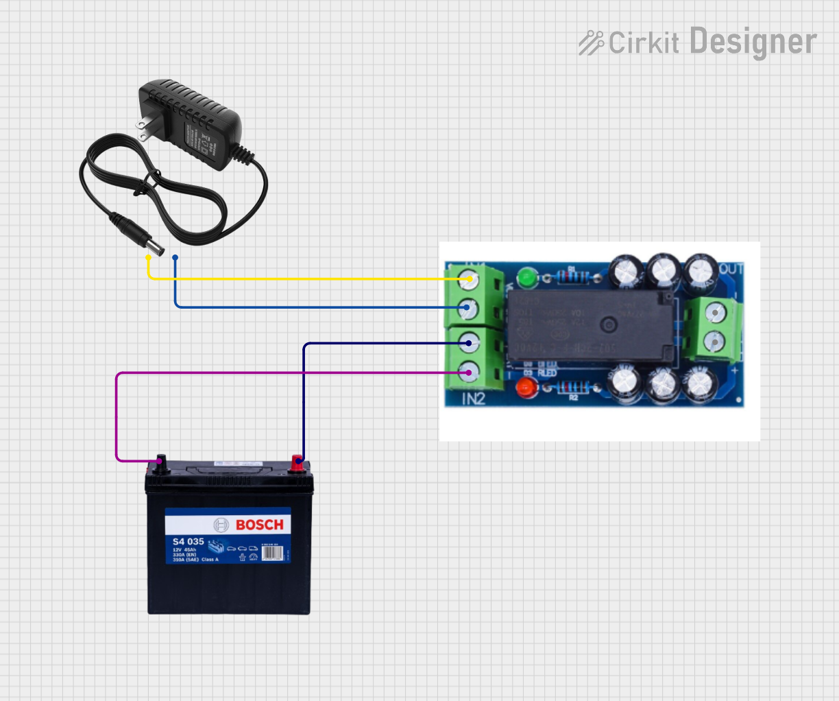 Open Project in Cirkit Designer
Explore Projects Built with SCR MCR100-6 back
Open Project in Cirkit DesignerOpen Project in Cirkit DesignerOpen Project in Cirkit DesignerOpen Project in Cirkit DesignerTechnical Specifications
The following table outlines the key technical specifications of the SCR MCR100-6:
| Parameter | Value |
|---|---|
| Maximum Repetitive Voltage (VRRM) | 400V |
| Maximum RMS On-State Current (IT(RMS)) | 0.8A |
| Peak Gate Trigger Current (IGT) | 200µA |
| Peak Gate Trigger Voltage (VGT) | 0.8V |
| Holding Current (IH) | 5mA |
| Peak Non-Repetitive Surge Current (ITSM) | 8A |
| Operating Temperature Range | -40°C to +110°C |
| Package Type | TO-92 |
Pin Configuration and Descriptions
The SCR MCR100-6 is housed in a TO-92 package with three pins. The pin configuration is as follows:
| Pin Number | Pin Name | Description |
|---|---|---|
| 1 | Gate | Trigger input to activate the SCR |
| 2 | Cathode | Connected to the negative terminal |
| 3 | Anode | Connected to the positive terminal |
Usage Instructions
How to Use the SCR MCR100-6 in a Circuit
Basic Circuit Setup:
- Connect the anode to the positive side of the power supply.
- Connect the cathode to the load, which is then connected to the negative side of the power supply.
- Use a resistor to limit the current to the gate pin. The gate is triggered by a small voltage signal to turn the SCR on.
Triggering the SCR:
- Apply a voltage signal (typically 0.8V or higher) to the gate pin to activate the SCR.
- Once triggered, the SCR will remain on as long as the current through the anode and cathode exceeds the holding current (5mA).
Turning Off the SCR:
- To turn off the SCR, reduce the current through the anode and cathode below the holding current. This can be achieved by interrupting the circuit or reducing the load.
Important Considerations and Best Practices
- Always use a current-limiting resistor with the gate pin to prevent damage to the SCR.
- Ensure the load current does not exceed the maximum RMS on-state current (0.8A) to avoid overheating.
- Use proper heat dissipation techniques if the SCR operates near its maximum ratings.
- For AC applications, the SCR will automatically turn off when the AC waveform crosses zero (natural commutation).
Example: Using SCR MCR100-6 with Arduino UNO
The SCR MCR100-6 can be controlled using an Arduino UNO to trigger the gate pin. Below is an example circuit and code to control a small DC load:
Circuit Setup
- Connect the anode to the positive terminal of the DC power supply.
- Connect the cathode to one terminal of the load, and the other terminal of the load to the negative terminal of the power supply.
- Connect the gate pin to a digital output pin of the Arduino through a 220Ω resistor.
Arduino Code
// SCR MCR100-6 Control with Arduino UNO
// Pin 9 is used to trigger the SCR gate

const int SCRGatePin = 9; // Define the pin connected to the SCR gate

void setup() {
  pinMode(SCRGatePin, OUTPUT); // Set the SCR gate pin as an output
}

void loop() {
  digitalWrite(SCRGatePin, HIGH); // Trigger the SCR by sending a HIGH signal
  delay(1000); // Keep the load ON for 1 second

  digitalWrite(SCRGatePin, LOW); // Stop triggering the SCR
  delay(1000); // Wait for 1 second before the next trigger
}
Notes:
- The SCR will remain on even after the gate signal is removed, as long as the load current exceeds the holding current.
- To turn off the SCR, interrupt the load current or reduce it below the holding current.
Troubleshooting and FAQs
Common Issues and Solutions
SCR Does Not Turn On:
- Ensure the gate signal voltage is at least 0.8V.
- Check the current-limiting resistor on the gate pin; it should allow sufficient current to trigger the SCR.
- Verify the polarity of the anode and cathode connections.
SCR Turns On but Does Not Turn Off:
- Ensure the load current drops below the holding current to turn off the SCR.
- For DC circuits, use an external switch to interrupt the load current.
SCR Overheats:
- Check if the load current exceeds the maximum RMS on-state current (0.8A).
- Use a heatsink or improve ventilation to dissipate heat.
Gate Signal Damages the SCR:
- Always use a current-limiting resistor with the gate pin to prevent excessive current.
FAQs
Q: Can the SCR MCR100-6 be used in AC circuits?
A: Yes, the SCR can be used in AC circuits. It will automatically turn off when the AC waveform crosses zero (natural commutation).
Q: What happens if the gate signal is continuously applied?
A: The SCR will remain on as long as the load current exceeds the holding current. Continuous gate signals are not necessary once the SCR is triggered.
Q: Can the SCR handle inductive loads?
A: Yes, but a snubber circuit (resistor-capacitor network) is recommended to protect the SCR from voltage spikes caused by inductive loads.
Q: How do I calculate the gate resistor value?
A: Use Ohm's law: ( R = \frac{V_{source} - V_{GT}}{I_{GT}} ), where ( V_{source} ) is the control voltage, ( V_{GT} ) is the gate trigger voltage, and ( I_{GT} ) is the gate trigger current.