
How to Use 3225 SMD Crystal (Breadboard Adapter): Examples, Pinouts, and Specs
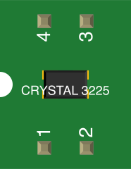
 Design with 3225 SMD Crystal (Breadboard Adapter) in Cirkit Designer
Introduction
The 3225 SMD Crystal is a surface-mount device designed to provide a stable and precise clock signal for microcontrollers, digital circuits, and other timing-critical applications. Its compact 3.2mm x 2.5mm package makes it ideal for space-constrained designs. However, due to its small size, direct use in prototyping can be challenging. The breadboard adapter solves this issue by converting the SMD package into a breadboard-friendly format, enabling easy integration into development setups.
Explore Projects Built with 3225 SMD Crystal (Breadboard Adapter)
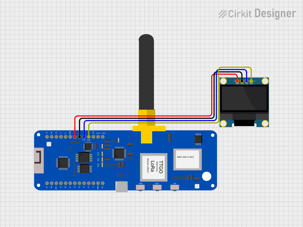 Open Project in Cirkit Designer
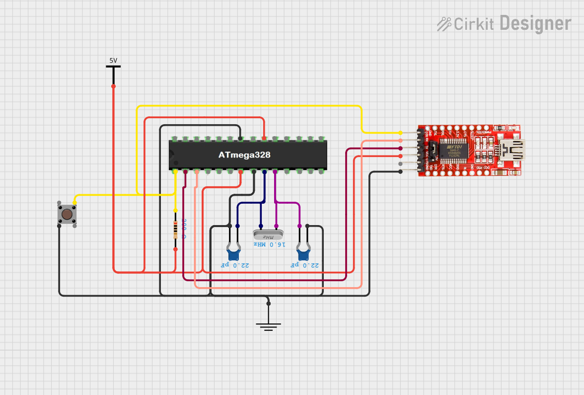 Open Project in Cirkit Designer
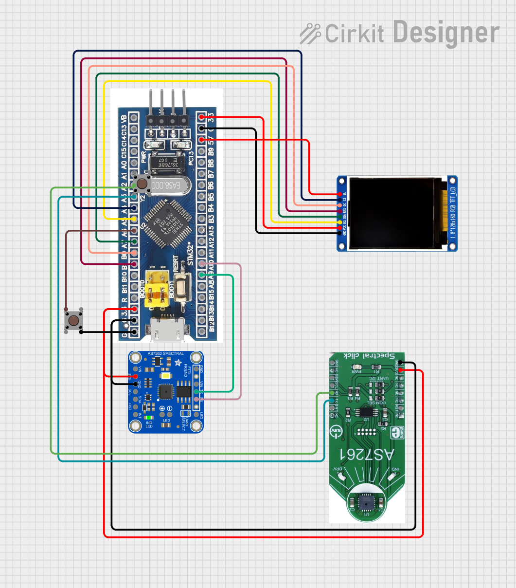 Open Project in Cirkit Designer
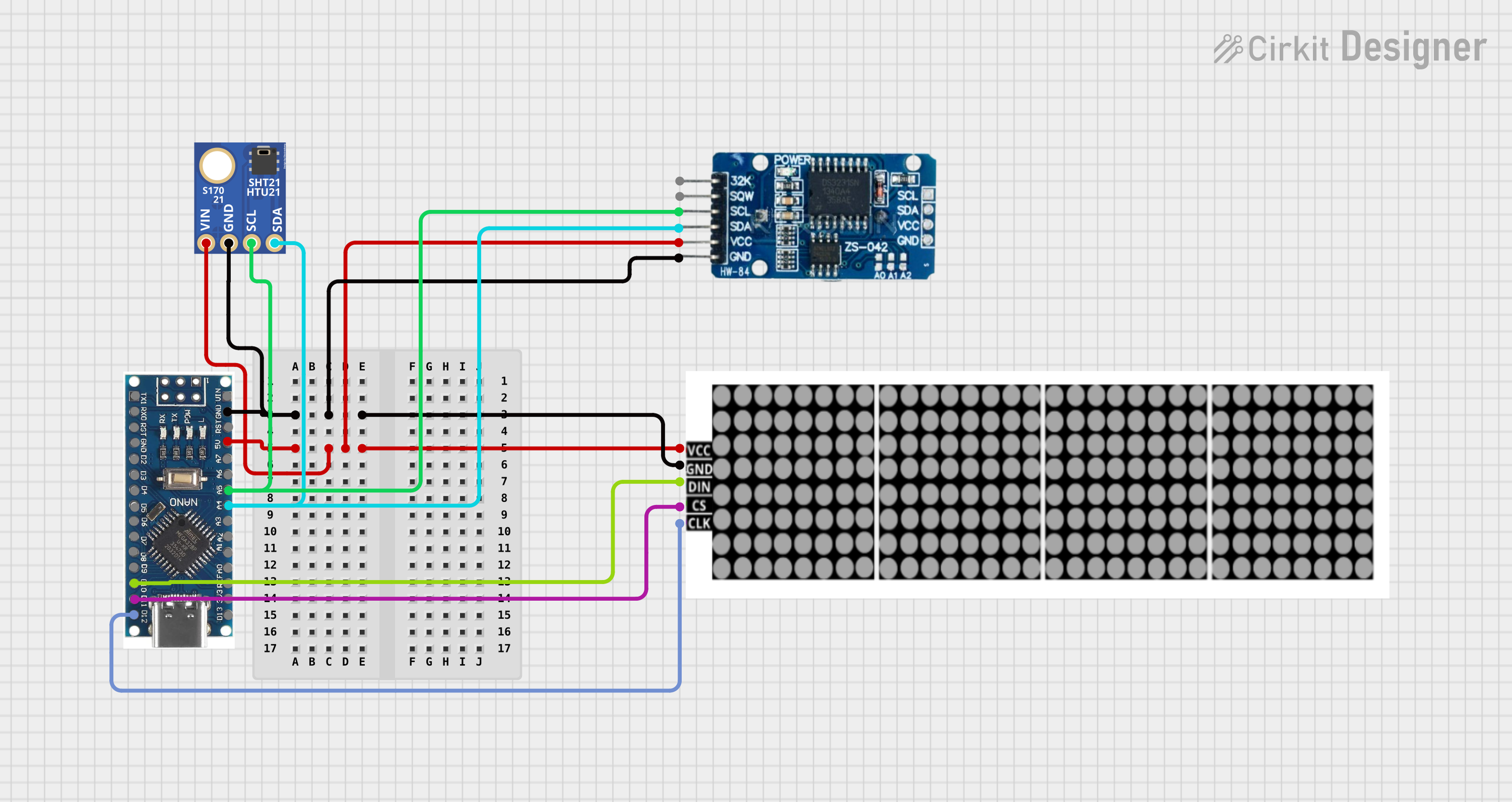 Open Project in Cirkit Designer
Explore Projects Built with 3225 SMD Crystal (Breadboard Adapter)
Open Project in Cirkit DesignerOpen Project in Cirkit DesignerOpen Project in Cirkit DesignerOpen Project in Cirkit DesignerCommon Applications
- Microcontroller clock sources (e.g., Arduino, STM32, ESP32)
- Timing circuits in digital systems
- Communication protocols requiring precise timing (e.g., UART, SPI, I2C)
- Frequency generation and signal processing
Technical Specifications
Crystal Specifications
| Parameter | Value |
|---|---|
| Package Size | 3.2mm x 2.5mm (3225 SMD) |
| Frequency Range | 8 MHz to 40 MHz (varies by model) |
| Frequency Tolerance | ±10 ppm to ±50 ppm |
| Load Capacitance | 8 pF to 20 pF |
| Operating Temperature | -20°C to +70°C (typical) |
| Drive Level | 10 µW to 100 µW |
Breadboard Adapter Specifications
| Parameter | Value |
|---|---|
| Adapter Dimensions | 20mm x 10mm |
| Pin Pitch | 2.54mm (breadboard standard) |
| Pin Count | 4 (GND, VCC, XTAL1, XTAL2) |
| Material | FR4 PCB with gold-plated pads |
Pin Configuration
| Pin Name | Description |
|---|---|
| GND | Ground connection for the crystal |
| VCC | Power supply for the crystal (optional, if required) |
| XTAL1 | Connect to the microcontroller's oscillator input |
| XTAL2 | Connect to the microcontroller's oscillator output |
Usage Instructions
Using the 3225 SMD Crystal with a Breadboard Adapter
- Insert the Adapter into the Breadboard: Place the adapter onto the breadboard, ensuring the pins align with the breadboard rows.
- Connect to the Microcontroller:
- Connect the
XTAL1andXTAL2pins to the corresponding oscillator pins on the microcontroller. - Connect
GNDto the ground rail of the breadboard. - If required, connect
VCCto the power rail (check your crystal's datasheet to confirm if this is necessary).
- Connect the
- Add Load Capacitors: Place external load capacitors (typically 18 pF) between each crystal pin (
XTAL1andXTAL2) and ground. These capacitors are essential for stable oscillation. - Power the Circuit: Ensure the microcontroller and crystal are powered within their specified voltage range.
Example: Using with Arduino UNO
The Arduino UNO requires an external crystal for precise timing. Below is an example of how to connect the 3225 SMD Crystal to the Arduino UNO:
Circuit Diagram
- Connect
XTAL1to Arduino pinXTAL1(pin 9 on the ATmega328P IC). - Connect
XTAL2to Arduino pinXTAL2(pin 10 on the ATmega328P IC). - Add two 18 pF capacitors between
XTAL1/XTAL2and GND.
Sample Code
The crystal itself does not require code to function, but it is used to drive the Arduino's internal clock. Below is an example sketch to verify the Arduino's timing:
// Blink LED to verify timing accuracy of the crystal
const int ledPin = 13; // Built-in LED pin on Arduino UNO

void setup() {
  pinMode(ledPin, OUTPUT); // Set LED pin as output
}

void loop() {
  digitalWrite(ledPin, HIGH); // Turn LED on
  delay(1000); // Wait for 1 second
  digitalWrite(ledPin, LOW); // Turn LED off
  delay(1000); // Wait for 1 second
}
Best Practices
- Always use the recommended load capacitors for your crystal to ensure stable operation.
- Avoid placing the crystal and its traces near high-frequency or noisy components.
- Keep the traces between the crystal and the microcontroller as short as possible to minimize parasitic capacitance.
Troubleshooting and FAQs
Common Issues
Crystal Not Oscillating:
- Cause: Missing or incorrect load capacitors.
- Solution: Verify the capacitor values match the crystal's datasheet specifications.
Microcontroller Not Booting:
- Cause: Incorrect connection of
XTAL1andXTAL2pins. - Solution: Double-check the wiring and ensure the crystal is connected to the correct pins.
- Cause: Incorrect connection of
Unstable Clock Signal:
- Cause: Excessive noise or long traces.
- Solution: Shorten the traces and keep the crystal away from noisy components.
FAQs
Q: Can I use the 3225 SMD Crystal without the breadboard adapter?
A: Yes, but you will need to solder it onto a custom PCB or use a breakout board for easier handling.
Q: What happens if I don't use load capacitors?
A: The crystal may fail to oscillate or produce an unstable clock signal, leading to erratic behavior in your circuit.
Q: Can I use this crystal with other microcontrollers?
A: Yes, the 3225 SMD Crystal is compatible with most microcontrollers, including STM32, ESP32, and PIC, as long as the frequency and load capacitance match the microcontroller's requirements.
Q: How do I determine the correct load capacitor values?
A: Refer to the crystal's datasheet for the specified load capacitance and calculate the capacitor values using the formula:
[
C_{load} = \frac{C_1 \cdot C_2}{C_1 + C_2} + C_{stray}
]
where (C_{stray}) is the stray capacitance of the PCB and traces (typically 3-5 pF).