
How to Use AVR_MINI_PROG: Examples, Pinouts, and Specs
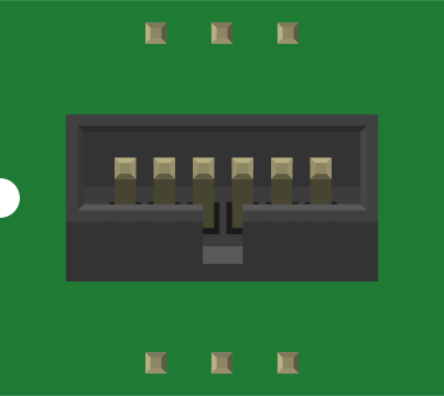
 Design with AVR_MINI_PROG in Cirkit Designer
Introduction
The AVR_MINI_PROG is a compact and versatile programmer designed for AVR microcontrollers. It enables users to upload code, debug programs, and perform firmware updates through a convenient USB interface. Its small form factor and ease of use make it an essential tool for hobbyists, students, and professionals working with AVR-based projects.
Explore Projects Built with AVR_MINI_PROG
 Open Project in Cirkit Designer
 Open Project in Cirkit Designer
 Open Project in Cirkit Designer
 Open Project in Cirkit Designer
Explore Projects Built with AVR_MINI_PROG
Open Project in Cirkit DesignerOpen Project in Cirkit DesignerOpen Project in Cirkit DesignerOpen Project in Cirkit DesignerCommon Applications and Use Cases
- Programming AVR microcontrollers in embedded systems
- Debugging and testing AVR-based circuits
- Bootloader installation and firmware updates
- Educational projects and prototyping
Technical Specifications
Key Technical Details
- Interface: USB 2.0 (Type-A or Type-C, depending on the model)
- Supported Microcontrollers: AVR family (e.g., ATmega, ATtiny series)
- Programming Protocols: ISP (In-System Programming), PDI, TPI
- Operating Voltage: 3.3V or 5V (selectable via jumper)
- Current Output: Up to 500mA (for powering target devices)
- Dimensions: 40mm x 20mm x 10mm
- LED Indicators: Power, Activity, and Error
Pin Configuration and Descriptions
The AVR_MINI_PROG features a 6-pin ISP header for connecting to AVR microcontrollers. Below is the pinout:
| Pin Number | Pin Name | Description |
|---|---|---|
| 1 | MISO | Master In Slave Out (data from AVR) |
| 2 | VCC | Power supply for the target device |
| 3 | SCK | Serial Clock |
| 4 | MOSI | Master Out Slave In (data to AVR) |
| 5 | RESET | Reset line for the AVR device |
| 6 | GND | Ground connection |
Usage Instructions
How to Use the AVR_MINI_PROG in a Circuit
Connect the Programmer to the Target Device:
- Use the 6-pin ISP cable to connect the AVR_MINI_PROG to the target microcontroller.
- Ensure the pin alignment matches the target device's ISP header.
Select the Voltage:
- Use the onboard jumper to select the appropriate voltage (3.3V or 5V) based on the target device's requirements.
Connect to a Computer:
- Plug the AVR_MINI_PROG into a USB port on your computer. The Power LED should light up.
Install Drivers:
- If required, install the necessary drivers for your operating system. These can typically be downloaded from the manufacturer's website.
Use Programming Software:
- Open your preferred AVR programming software (e.g., AVRDUDE, Atmel Studio).
- Select the appropriate programmer type and communication port.
- Upload your code or perform debugging as needed.
Important Considerations and Best Practices
- Always verify the voltage requirements of your target device before connecting the programmer.
- Avoid connecting or disconnecting the programmer while the target device is powered.
- Use a high-quality USB cable to ensure reliable communication.
- If using with an Arduino UNO or similar boards, ensure the board is configured for ISP programming.
Example Code for Arduino UNO
Below is an example of using the AVR_MINI_PROG to upload a simple "Blink" sketch to an Arduino UNO via ISP:
// This example assumes you have connected the AVR_MINI_PROG to the Arduino UNO
// via the ISP header and selected the correct voltage (5V for Arduino UNO).

// Open the Arduino IDE and go to Tools > Programmer > "AVRISP mkII".
// Then, select Tools > Burn Bootloader to prepare the board for ISP programming.

// Example Blink Sketch
void setup() {
  pinMode(13, OUTPUT); // Set pin 13 (built-in LED) as an output
}

void loop() {
  digitalWrite(13, HIGH); // Turn the LED on
  delay(1000);            // Wait for 1 second
  digitalWrite(13, LOW);  // Turn the LED off
  delay(1000);            // Wait for 1 second
}
Troubleshooting and FAQs
Common Issues and Solutions
The Programmer is Not Detected by the Computer:
- Ensure the USB cable is properly connected.
- Check if the required drivers are installed.
- Try using a different USB port or cable.
Target Device is Not Responding:
- Verify the ISP cable connections and pin alignment.
- Ensure the correct voltage is selected (3.3V or 5V).
- Check if the target device is powered and functional.
Error During Code Upload:
- Confirm the correct programmer type is selected in the software.
- Ensure no other devices are using the same communication port.
- Reset the target device and try again.
FAQs
Can the AVR_MINI_PROG power the target device? Yes, it can supply up to 500mA to the target device. Ensure the current draw does not exceed this limit.
Is the AVR_MINI_PROG compatible with non-AVR microcontrollers? No, it is specifically designed for AVR microcontrollers and may not work with other architectures.
How do I update the firmware on the AVR_MINI_PROG? Firmware updates can be performed using the manufacturer's utility software. Follow the instructions provided on their website.
By following this documentation, you can effectively use the AVR_MINI_PROG for programming and debugging AVR microcontrollers.