How to Use Servo: Examples, Pinouts, and Specs
Introduction
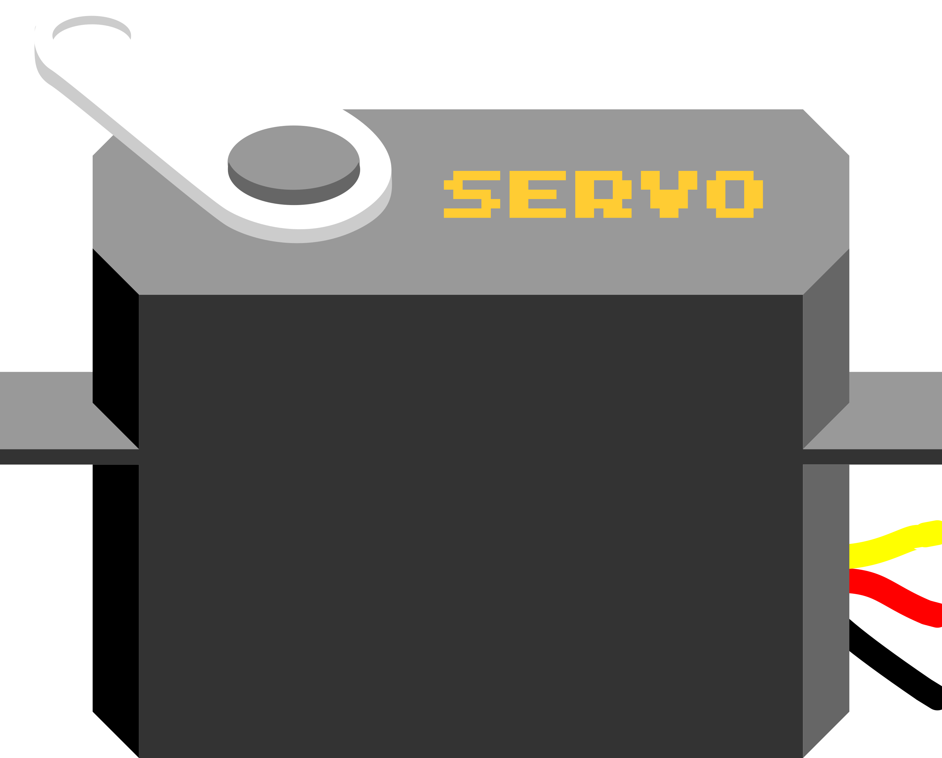
A servo motor is an electromechanical device that provides precise control of angular or linear position, velocity, and acceleration. It is commonly used in applications such as robotics, model aircraft, and any system where controlled motion is required. The servo consists of a small DC motor, a gearbox for torque multiplication, and control circuitry for position feedback. The control signal is usually a PWM (Pulse Width Modulation) signal, which dictates the position of the servo shaft.
Explore Projects Built with Servo

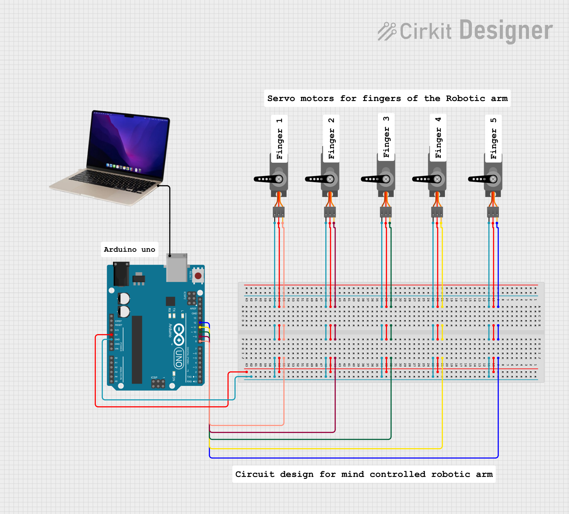
Explore Projects Built with Servo
Technical Specifications
Key Technical Details
- Voltage Range: Typically 4.8V to 6V for standard servos.
- Current Consumption: Varies with load, typically between 10mA (idle) to 1A (stalled).
- Torque: Depends on the model, can range from 1.5 kg-cm to 20 kg-cm or more.
- Speed: Varies by model, typically from 0.10 to 0.20 seconds per 60-degree movement.
- Rotation Angle: Usually 0 to 180 degrees, some servos offer more extended ranges.
Pin Configuration and Descriptions
| Pin Number | Color (Common) | Description |
|---|---|---|
| 1 | Brown/Black | Ground (-) |
| 2 | Red | Power Supply (V+) |
| 3 | Orange/Yellow | Control Signal (PWM input) |
Usage Instructions
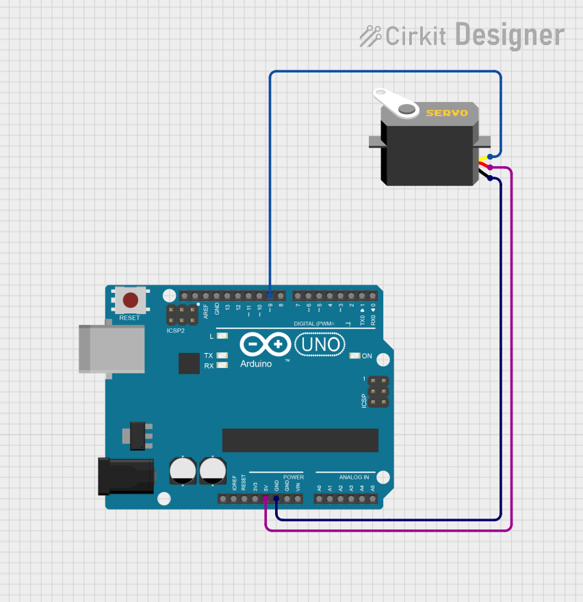
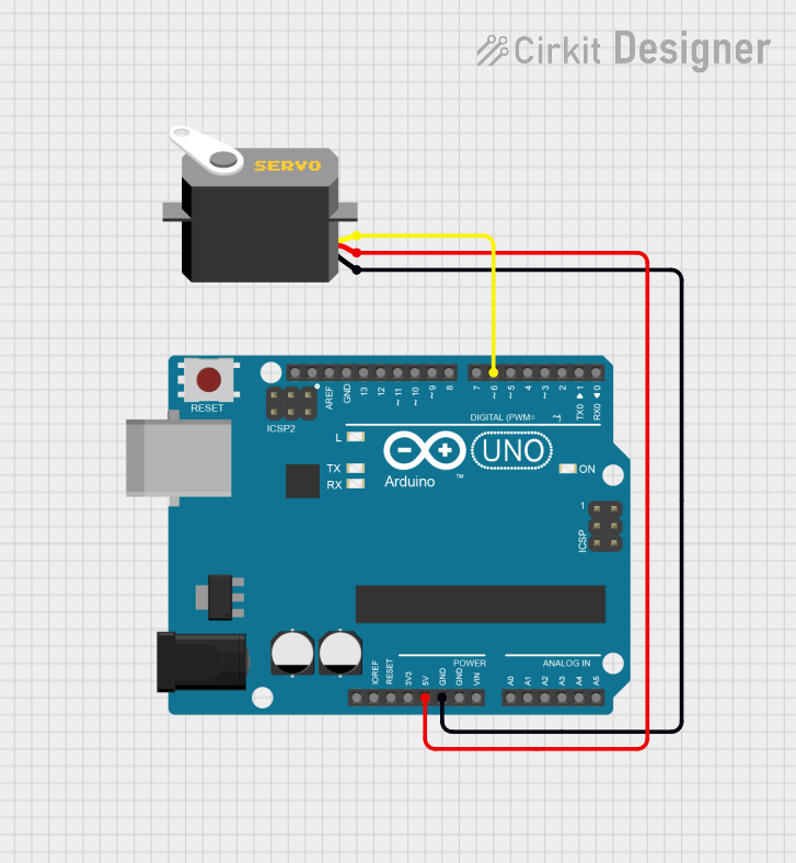
Connecting to a Circuit
- Power Supply: Connect the power supply to the servo's red wire (V+) and the ground to the brown or black wire. Ensure the voltage is within the servo's specified range.
- Control Signal: Connect the control signal wire (orange or yellow) to a PWM-capable pin on your microcontroller.
Best Practices
- Power Supply: Use a dedicated power supply for servos to prevent voltage drops, which can cause erratic behavior.
- Signal Isolation: Use a separate ground for the control signal to minimize electrical noise.
- Mounting: Secure the servo to prevent movement and ensure accurate operation.
- Load: Do not exceed the servo's maximum torque rating to avoid damage.
Example Code for Arduino UNO
#include <Servo.h>

Servo myservo;  // create servo object to control a servo

void setup() {
  myservo.attach(9);  // attaches the servo on pin 9 to the servo object
}

void loop() {
  myservo.write(90);  // sets the servo position to 90 degrees
  delay(1000);        // waits for the servo to reach the position
  myservo.write(0);   // sets the servo back to 0 degrees
  delay(1000);        // waits for the servo to reach the position
}
Troubleshooting and FAQs
Common Issues
- Servo Jitter: This can be caused by an inadequate power supply or electrical noise. Ensure a stable power source and proper grounding.
- Limited Movement: If the servo does not achieve its full range, check the PWM signal's pulse width and adjust it accordingly.
- Overheating: Continuous operation under high load can cause overheating. Allow the servo to cool down.
FAQs
Q: Can I control a servo with a constant DC voltage? A: No, servos require a PWM signal for position control.
Q: How do I reverse the direction of a servo? A: You can reverse the direction by swapping the control signal's high and low pulse widths in your code.
Q: What is the maximum length for servo control wires? A: It depends on the quality of the wires and the operating environment, but it's generally recommended to keep the wires as short as possible to minimize voltage drops and noise.
Remember to always consult the datasheet specific to your servo model for the most accurate and detailed information.