Cirkit Designer Logo
Cirkit Designer
Your all-in-one circuit design IDE
Home / 
Component Documentation

How to Use SparkFun AST-CAN485: Examples, Pinouts, and Specs

Image of SparkFun AST-CAN485
Cirkit Designer LogoDesign with SparkFun AST-CAN485 in Cirkit Designer

Introduction

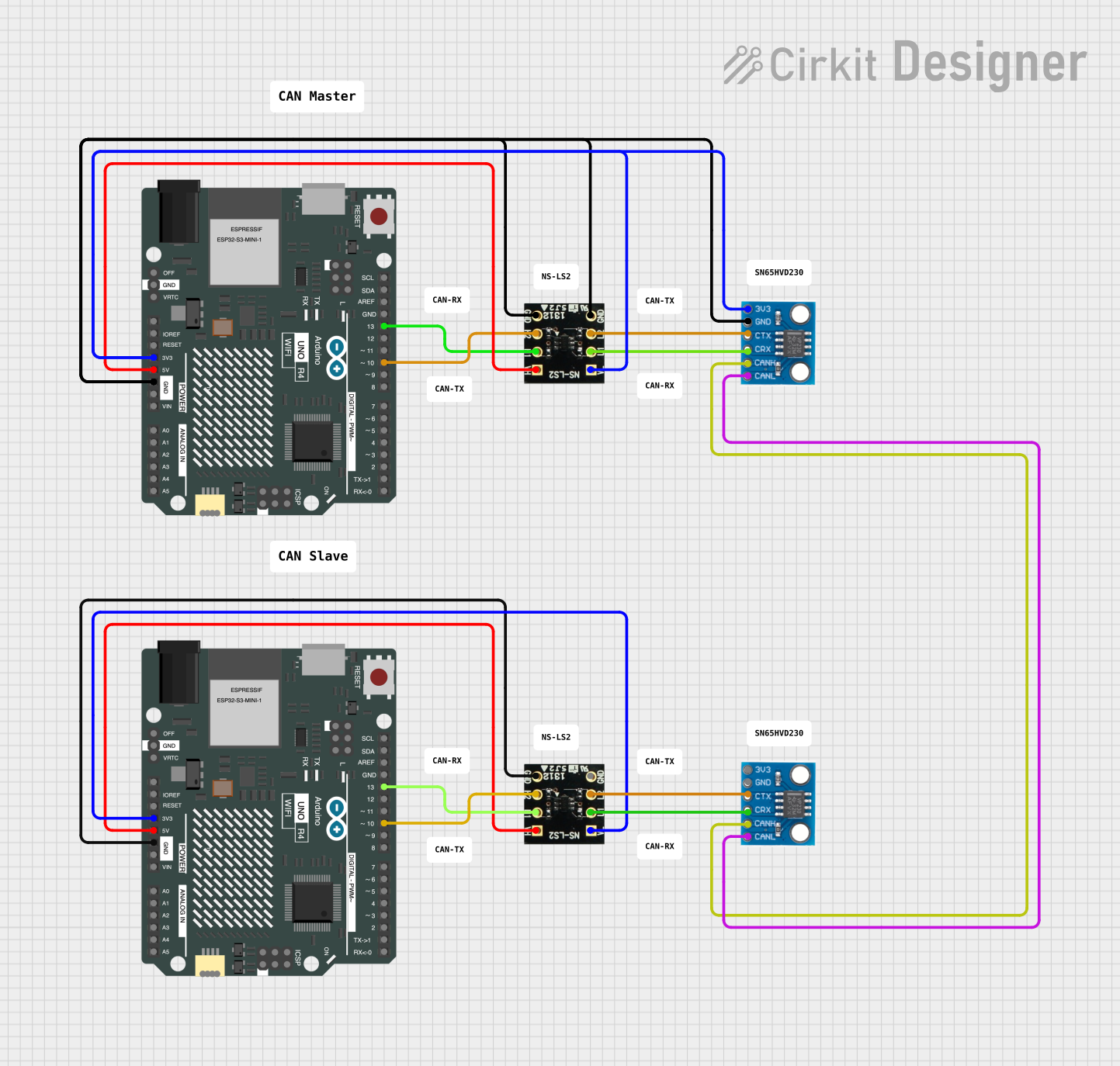
The SparkFun AST-CAN485 is a versatile shield designed for Arduino-compatible boards, enabling communication over CAN (Controller Area Network) and RS485 networks. This shield is particularly useful in automotive and industrial environments where robust and reliable communication is essential. The AST-CAN485 integrates both CAN and RS485 transceivers, offering a bridge between these two popular communication protocols.

Explore Projects Built with SparkFun AST-CAN485

Use Cirkit Designer to design, explore, and prototype these projects online. Some projects support real-time simulation. Click "Open Project" to start designing instantly!
ESP32C3-Based Soil Monitoring System with RS485 Communication
Image of 3-slave-soil: A project utilizing SparkFun AST-CAN485 in a practical application
This circuit features an ESP32C3 Supermini microcontroller interfaced with an RS485 transceiver module, allowing for serial communication over long distances. A toggle switch and a pushbutton are connected to the ESP32C3 for user input, with a pull-up resistor on the toggle switch. Additionally, the circuit includes an NPK Soil Sensor connected to the RS485 module for measuring soil nutrient levels, with power supplied to the sensor and RS485 module from the ESP32C3.
Cirkit Designer LogoOpen Project in Cirkit Designer
ESP-32 and Arduino Uno R3 Based RS485 Communication System with Ultrasonic Sensing and Motor Control
Image of simulatorp_roject: A project utilizing SparkFun AST-CAN485 in a practical application
This circuit features two RS485 transceivers interfaced with an ESP-32 microcontroller and an Arduino Uno R3, enabling serial communication over a differential bus. The Arduino also controls a green and a red LED, an HC-SR04 ultrasonic sensor, and a relay that switches a DC motor on and off. The ESP-32 is likely used for wireless communication or processing, while the Arduino manages sensor readings, motor control, and status indication through the LEDs.
Cirkit Designer LogoOpen Project in Cirkit Designer
Arduino UNO WiFi CAN Bus Interface with Sensor/Actuator Module
Image of CAN : SN65HVD230 via NS-LS2(LevelConverter)2: A project utilizing SparkFun AST-CAN485 in a practical application
This circuit features two Arduino UNO R4 WiFi microcontrollers interfaced with NS-LS2 light sensors and CAN_SN65HVD230 CAN bus transceivers. The Arduinos are configured to read light intensity data from the NS-LS2 sensors and communicate with each other over a CAN network, likely for a distributed sensing application. Power distribution is managed with 3.3V and 5V connections to the respective components, and the ground connections are shared across the devices to complete the circuit.
Cirkit Designer LogoOpen Project in Cirkit Designer
ESP32 and MCP2515 CAN Bus Interface with Potentiometer Control
Image of EngineNodeWiringDiagram: A project utilizing SparkFun AST-CAN485 in a practical application
This circuit features an ESP32 microcontroller interfaced with an MCP2515 CAN controller and a potentiometer. The ESP32 reads the analog output from the potentiometer and communicates with the MCP2515 via SPI to potentially transmit or receive CAN messages.
Cirkit Designer LogoOpen Project in Cirkit Designer

Explore Projects Built with SparkFun AST-CAN485

Use Cirkit Designer to design, explore, and prototype these projects online. Some projects support real-time simulation. Click "Open Project" to start designing instantly!
Image of 3-slave-soil: A project utilizing SparkFun AST-CAN485 in a practical application
ESP32C3-Based Soil Monitoring System with RS485 Communication
This circuit features an ESP32C3 Supermini microcontroller interfaced with an RS485 transceiver module, allowing for serial communication over long distances. A toggle switch and a pushbutton are connected to the ESP32C3 for user input, with a pull-up resistor on the toggle switch. Additionally, the circuit includes an NPK Soil Sensor connected to the RS485 module for measuring soil nutrient levels, with power supplied to the sensor and RS485 module from the ESP32C3.
Cirkit Designer LogoOpen Project in Cirkit Designer
Image of simulatorp_roject: A project utilizing SparkFun AST-CAN485 in a practical application
ESP-32 and Arduino Uno R3 Based RS485 Communication System with Ultrasonic Sensing and Motor Control
This circuit features two RS485 transceivers interfaced with an ESP-32 microcontroller and an Arduino Uno R3, enabling serial communication over a differential bus. The Arduino also controls a green and a red LED, an HC-SR04 ultrasonic sensor, and a relay that switches a DC motor on and off. The ESP-32 is likely used for wireless communication or processing, while the Arduino manages sensor readings, motor control, and status indication through the LEDs.
Cirkit Designer LogoOpen Project in Cirkit Designer
Image of CAN : SN65HVD230 via NS-LS2(LevelConverter)2: A project utilizing SparkFun AST-CAN485 in a practical application
Arduino UNO WiFi CAN Bus Interface with Sensor/Actuator Module
This circuit features two Arduino UNO R4 WiFi microcontrollers interfaced with NS-LS2 light sensors and CAN_SN65HVD230 CAN bus transceivers. The Arduinos are configured to read light intensity data from the NS-LS2 sensors and communicate with each other over a CAN network, likely for a distributed sensing application. Power distribution is managed with 3.3V and 5V connections to the respective components, and the ground connections are shared across the devices to complete the circuit.
Cirkit Designer LogoOpen Project in Cirkit Designer
Image of EngineNodeWiringDiagram: A project utilizing SparkFun AST-CAN485 in a practical application
ESP32 and MCP2515 CAN Bus Interface with Potentiometer Control
This circuit features an ESP32 microcontroller interfaced with an MCP2515 CAN controller and a potentiometer. The ESP32 reads the analog output from the potentiometer and communicates with the MCP2515 via SPI to potentially transmit or receive CAN messages.
Cirkit Designer LogoOpen Project in Cirkit Designer

Common Applications and Use Cases

  • Automotive diagnostics and networking
  • Industrial automation and control systems
  • Robotics communication interfaces
  • Data logging and telemetry

Technical Specifications

Key Technical Details

  • Operating Voltage: 3.3V to 5V
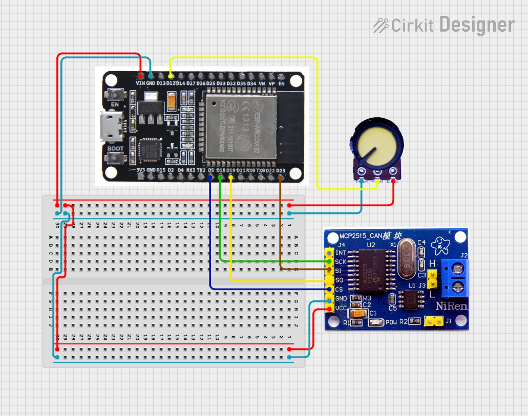
  • CAN Controller: MCP2515
  • CAN Transceiver: MCP2551
  • RS485 Transceiver: SP3485
  • CAN 2.0B up to 1 Mb/s
  • High speed SPI Interface (10 MHz)

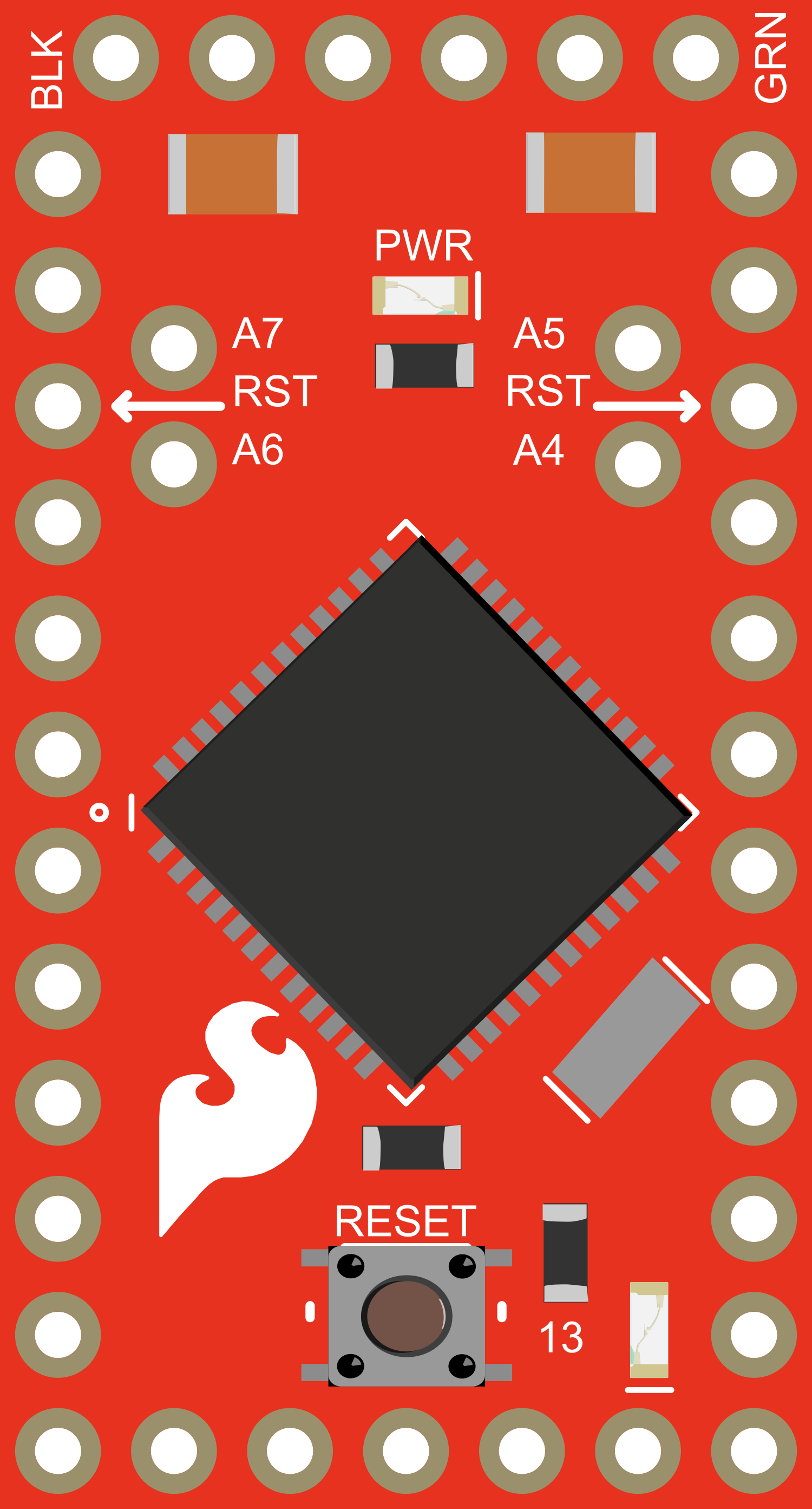
Pin Configuration and Descriptions

Pin Number Function Description
D2 INT Interrupt pin for CAN controller
D9 CS Chip select for CAN controller
D10 RS485 DE/RE RS485 Driver Enable / Receiver Enable
D11 MOSI SPI communication with CAN controller
D12 MISO SPI communication with CAN controller
D13 SCK SPI communication with CAN controller
A4 RS485 DI RS485 Data In
A5 RS485 RO RS485 Data Out

Usage Instructions

How to Use the Component in a Circuit

  1. Mounting the Shield: Attach the SparkFun AST-CAN485 shield onto your Arduino-compatible board ensuring proper alignment of pins.

  2. Wiring for CAN: Connect the CANH and CANL screw terminals to your CAN network. Ensure that the network has proper termination resistors.

  3. Wiring for RS485: Connect the A and B screw terminals to your RS485 network. Ensure that the network is properly terminated.

  4. Power Supply: Ensure that your Arduino board is powered with a suitable power source that can provide adequate current for both the Arduino and the AST-CAN485 shield.

Important Considerations and Best Practices

  • Use twisted-pair cables for CAN and RS485 to reduce electromagnetic interference.
  • Ensure that the shield is properly seated on the Arduino board to avoid misalignment of pins.
  • When working with automotive systems, be aware of the potential for electrical noise and take appropriate measures to shield your connections.
  • Always follow proper ESD precautions when handling the shield to prevent damage to sensitive components.

Example Code for Arduino UNO

#include <SPI.h>
#include <mcp_can.h>

// Initialize CAN controller with CS pin D9
MCP_CAN CAN(D9);

void setup() {
  Serial.begin(115200);

  // Initialize CAN bus at 500 kbps
  if (CAN.begin(MCP_ANY, CAN_500KBPS, MCP_8MHZ) == CAN_OK) {
    Serial.println("CAN bus shield initialized successfully!");
  } else {
    Serial.println("Error initializing CAN bus shield!");
  }
}

void loop() {
  // Check for incoming messages
  if (CAN_MSGAVAIL == CAN.checkReceive()) {
    long unsigned int rxId;
    unsigned char len = 0;
    unsigned char rxBuf[8];

    // Read data: len = data length, buf = data byte(s)
    CAN.readMsgBuf(&len, rxBuf);
    rxId = CAN.getCanId();

    Serial.print("Message ID: ");
    Serial.print(rxId, HEX);
    Serial.print(" Data: ");
    for (int i = 0; i < len; i++) {
      Serial.print(rxBuf[i], HEX);
      Serial.print(" ");
    }
    Serial.println();
  }
}

Troubleshooting and FAQs

Common Issues Users Might Face

  • CAN/RS485 Not Communicating: Ensure that all connections are secure and the network is properly terminated with resistors.
  • No Data Being Received: Check that the interrupt and CS pins are correctly defined in your code.
  • Errors in Serial Monitor: Verify that the baud rate of the Serial Monitor matches the baud rate defined in your sketch.

Solutions and Tips for Troubleshooting

  • Double-check wiring and pin connections.
  • Use the CAN_OK return code to check for successful initialization of the CAN controller.
  • Ensure that the SPI clock does not exceed the maximum frequency supported by the CAN controller.
  • Review the example code and library documentation for additional functions and diagnostic tools.

FAQs

Q: Can I use the AST-CAN485 shield with a 3.3V Arduino board? A: Yes, the shield is compatible with both 3.3V and 5V systems.

Q: How do I change the CAN bus speed? A: Modify the CAN.begin() function in your code to set the desired speed (e.g., CAN_250KBPS).

Q: What is the maximum length for a CAN or RS485 network? A: The maximum length depends on the baud rate and quality of the cables but can be up to 1200 meters for RS485 and 40 meters for CAN at 1 Mbps.

Q: How do I handle multiple nodes on a CAN network? A: Each node should have a unique ID, and the network should be properly terminated at both ends.

For further assistance, consult the SparkFun AST-CAN485 datasheet and the libraries' documentation.