How to Use ESP32-Wroom-HW-394: Examples, Pinouts, and Specs
Introduction
The ESP32-Wroom-HW-394 is a powerful microcontroller module designed for IoT (Internet of Things) applications. It features integrated Wi-Fi and Bluetooth capabilities, making it ideal for wireless communication and smart device projects. With its dual-core processing power and a wide range of GPIO (General Purpose Input/Output) pins, the ESP32-Wroom-HW-394 is versatile and suitable for a variety of applications, including home automation, wearable devices, and industrial IoT systems.
Explore Projects Built with ESP32-Wroom-HW-394


Explore Projects Built with ESP32-Wroom-HW-394
Common Applications and Use Cases
- Smart home devices (e.g., smart lights, thermostats)
- Wireless sensor networks
- Industrial automation and monitoring
- Wearable technology
- Robotics and drones
- Real-time data logging and cloud integration
Technical Specifications
The ESP32-Wroom-HW-394 is packed with features that make it a robust and flexible choice for developers. Below are its key technical specifications:
| Specification | Details |
|---|---|
| Microcontroller | Dual-core Xtensa® 32-bit LX6 processor |
| Clock Speed | Up to 240 MHz |
| Flash Memory | 4 MB (external) |
| SRAM | 520 KB |
| Wireless Connectivity | Wi-Fi 802.11 b/g/n, Bluetooth v4.2 + BLE |
| Operating Voltage | 3.3V |
| GPIO Pins | 34 (multipurpose, including ADC, DAC, PWM, I2C, SPI, UART) |
| ADC Channels | 18 (12-bit resolution) |
| DAC Channels | 2 |
| Communication Interfaces | UART, SPI, I2C, I2S, CAN, Ethernet MAC |
| Power Consumption | Ultra-low power consumption in deep sleep mode (as low as 10 µA) |
| Operating Temperature | -40°C to 85°C |
| Dimensions | 18 mm x 25.5 mm |
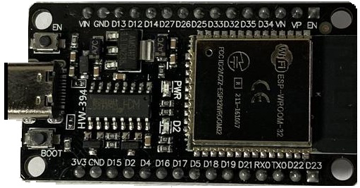
Pin Configuration and Descriptions
The ESP32-Wroom-HW-394 has a total of 38 pins. Below is a table describing the key pins and their functions:
| Pin Number | Pin Name | Function |
|---|---|---|
| 1 | EN | Enable pin. Pull high to enable the module. |
| 2 | IO0 | GPIO0. Can be used for general I/O or boot mode selection. |
| 3 | IO2 | GPIO2. General-purpose I/O. |
| 4 | IO4 | GPIO4. General-purpose I/O. |
| 5 | IO5 | GPIO5. General-purpose I/O. |
| 6 | IO12 | GPIO12. Can be used as ADC or general-purpose I/O. |
| 7 | IO13 | GPIO13. Can be used as ADC or general-purpose I/O. |
| 8 | IO14 | GPIO14. Can be used as ADC or general-purpose I/O. |
| 9 | IO15 | GPIO15. Can be used as ADC or general-purpose I/O. |
| 10 | IO16 | GPIO16. General-purpose I/O. |
| 11 | GND | Ground. Connect to the ground of the power supply. |
| 12 | 3V3 | 3.3V power input. |
| 13 | TXD0 | UART0 Transmit pin. |
| 14 | RXD0 | UART0 Receive pin. |
| 15 | ADC1_CH0 | ADC Channel 0. Can be used for analog input. |
| 16 | DAC1 | DAC Channel 1. Can be used for analog output. |
For a complete pinout, refer to the official datasheet.
Usage Instructions
How to Use the ESP32-Wroom-HW-394 in a Circuit
- Powering the Module:
- Connect the
3V3pin to a 3.3V power source. - Connect the
GNDpin to the ground of the power source.
- Connect the
- Programming the Module:
- Use a USB-to-Serial adapter to connect the module to your computer.
- Connect the
TXD0pin to the RX pin of the adapter and theRXD0pin to the TX pin of the adapter. - Use the
ENpin to reset the module if needed.
- Interfacing with Peripherals:
- Use the GPIO pins for digital input/output.
- Use ADC pins for analog input and DAC pins for analog output.
- Use I2C, SPI, or UART for communication with other devices.
Important Considerations and Best Practices
- Voltage Levels: Ensure all connected devices operate at 3.3V logic levels to avoid damaging the module.
- Deep Sleep Mode: Use deep sleep mode to conserve power in battery-powered applications.
- Antenna Placement: Ensure the onboard antenna has sufficient clearance from metal objects to avoid interference.
- Boot Mode: To enter bootloader mode, hold GPIO0 low while resetting the module.
Example Code for Arduino UNO
The ESP32-Wroom-HW-394 can be programmed using the Arduino IDE. Below is an example of how to connect the module to Wi-Fi and blink an LED:
#include <WiFi.h> // Include the WiFi library for ESP32

const char* ssid = "Your_SSID";       // Replace with your Wi-Fi network name
const char* password = "Your_Password"; // Replace with your Wi-Fi password
const int ledPin = 2;                 // GPIO2 is connected to the onboard LED

void setup() {
  Serial.begin(115200);               // Initialize serial communication
  pinMode(ledPin, OUTPUT);            // Set GPIO2 as an output pin

  // Connect to Wi-Fi
  Serial.print("Connecting to Wi-Fi");
  WiFi.begin(ssid, password);
  while (WiFi.status() != WL_CONNECTED) {
    delay(500);
    Serial.print(".");
  }
  Serial.println("\nWi-Fi connected!");
  Serial.print("IP Address: ");
  Serial.println(WiFi.localIP());     // Print the module's IP address
}

void loop() {
  digitalWrite(ledPin, HIGH);         // Turn the LED on
  delay(1000);                        // Wait for 1 second
  digitalWrite(ledPin, LOW);          // Turn the LED off
  delay(1000);                        // Wait for 1 second
}
Troubleshooting and FAQs
Common Issues and Solutions
Module Not Connecting to Wi-Fi:
- Ensure the SSID and password are correct.
- Check if the Wi-Fi network is within range.
- Verify that the module's antenna is not obstructed.
Module Not Responding:
- Check the power supply voltage (must be 3.3V).
- Ensure the
ENpin is pulled high. - Verify the connections to the USB-to-Serial adapter.
GPIO Pins Not Working:
- Ensure the pins are not being used for other functions (e.g., boot mode).
- Check for short circuits or incorrect wiring.
FAQs
Q: Can the ESP32-Wroom-HW-394 operate on 5V?
A: No, the module operates at 3.3V. Using 5V can damage the module.
Q: How do I update the firmware?
A: Use the ESP32 Flash Download Tool or the Arduino IDE to upload new firmware.
Q: Can I use the ESP32-Wroom-HW-394 with a battery?
A: Yes, you can use a 3.7V LiPo battery with a voltage regulator to provide 3.3V to the module.
Q: What is the maximum range of the Wi-Fi?
A: The Wi-Fi range is approximately 50 meters indoors and 200 meters outdoors, depending on the environment.