
How to Use Adafruit ItsyBitsy M4: Examples, Pinouts, and Specs
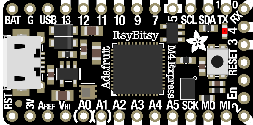
 Design with Adafruit ItsyBitsy M4 in Cirkit Designer
Introduction
The Adafruit ItsyBitsy M4 (Manufacturer Part ID: 3800) is a compact and powerful microcontroller board designed for embedded applications. It is based on the ATSAMD51 chip, featuring a 120 MHz ARM Cortex-M4 processor with floating-point support, 512KB of RAM, and 2MB of flash storage. Despite its small size, the ItsyBitsy M4 offers robust performance and a wide range of features, making it ideal for projects where space is limited but processing power is essential.
Explore Projects Built with Adafruit ItsyBitsy M4
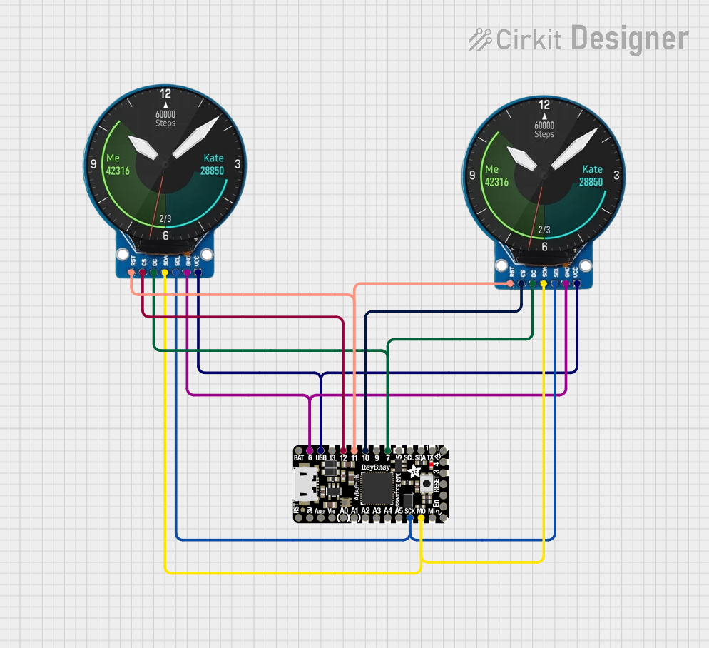 Open Project in Cirkit Designer
 Open Project in Cirkit Designer
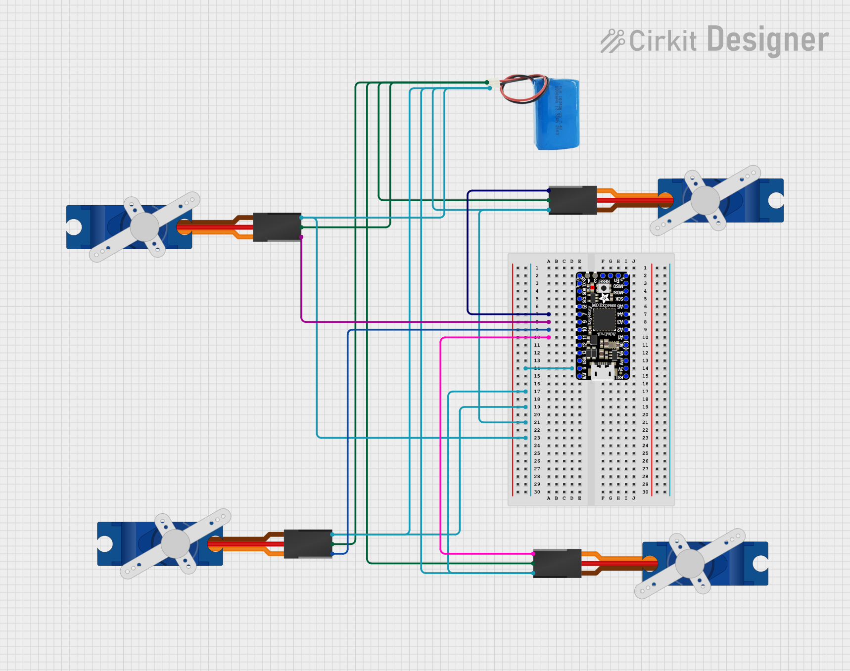 Open Project in Cirkit Designer
 Open Project in Cirkit Designer
Explore Projects Built with Adafruit ItsyBitsy M4
Open Project in Cirkit DesignerOpen Project in Cirkit DesignerOpen Project in Cirkit DesignerOpen Project in Cirkit DesignerCommon Applications
- Wearable electronics
- IoT (Internet of Things) devices
- Robotics and automation
- Data logging and sensor interfacing
- Prototyping compact embedded systems
Technical Specifications
Key Technical Details
| Specification | Value |
|---|---|
| Microcontroller | ATSAMD51 Cortex-M4 @ 120 MHz |
| RAM | 512KB |
| Flash Storage | 2MB |
| Operating Voltage | 3.3V |
| Input Voltage (VIN) | 3.3V to 6V |
| Digital I/O Pins | 23 |
| PWM Pins | 13 |
| Analog Input Pins | 6 |
| Analog Output Pins | 1 (DAC) |
| Communication Interfaces | UART, I2C, SPI |
| USB Interface | USB 2.0 (Micro-B connector) |
| Dimensions | 36mm x 18mm x 4mm |
Pin Configuration and Descriptions
The Adafruit ItsyBitsy M4 has a total of 23 GPIO pins, which can be configured for various functions. Below is the pinout description:
| Pin Number | Label | Function(s) | Notes |
|---|---|---|---|
| 1 | GND | Ground | Common ground for the circuit |
| 2 | 3V | 3.3V Power Output | Regulated 3.3V output |
| 3 | A0 | Analog Input / Digital I/O | Can be used as ADC or GPIO |
| 4 | A1 | Analog Input / Digital I/O | Can be used as ADC or GPIO |
| 5 | A2 | Analog Input / Digital I/O | Can be used as ADC or GPIO |
| 6 | A3 | Analog Input / Digital I/O | Can be used as ADC or GPIO |
| 7 | A4 (SDA) | Analog Input / I2C Data Line | I2C-compatible pin |
| 8 | A5 (SCL) | Analog Input / I2C Clock Line | I2C-compatible pin |
| 9 | D0 (RX) | Digital I/O / UART Receive | UART RX pin |
| 10 | D1 (TX) | Digital I/O / UART Transmit | UART TX pin |
| 11 | D2 | Digital I/O | General-purpose GPIO |
| 12 | D3 | Digital I/O / PWM | PWM-capable pin |
| 13 | D4 | Digital I/O | General-purpose GPIO |
| 14 | D5 | Digital I/O / PWM | PWM-capable pin |
| 15 | D6 | Digital I/O / PWM | PWM-capable pin |
| 16 | D7 | Digital I/O | General-purpose GPIO |
| 17 | D8 | Digital I/O | General-purpose GPIO |
| 18 | D9 | Digital I/O / PWM | PWM-capable pin |
| 19 | D10 | Digital I/O / PWM | PWM-capable pin |
| 20 | D11 | Digital I/O / SPI MOSI | SPI-compatible pin |
| 21 | D12 | Digital I/O / SPI MISO | SPI-compatible pin |
| 22 | D13 | Digital I/O / SPI SCK / LED | SPI-compatible pin, onboard LED |
| 23 | RST | Reset | Resets the microcontroller |
Usage Instructions
How to Use the Component in a Circuit
Powering the Board:
- The ItsyBitsy M4 can be powered via the USB Micro-B connector or through the VIN pin (3.3V to 6V). Ensure the power source is stable and within the specified voltage range.
- The onboard voltage regulator provides a 3.3V output for powering external components.
Connecting Peripherals:
- Use the GPIO pins for interfacing with sensors, actuators, or other devices. Configure the pins as input or output in your code.
- For analog sensors, connect them to the analog input pins (A0–A5). The ADC supports 12-bit resolution.
Programming the Board:
- The ItsyBitsy M4 is compatible with the Arduino IDE. Install the Adafruit SAMD Boards package via the Arduino Board Manager.
- Connect the board to your computer using a USB Micro-B cable. Select the correct board and port in the Arduino IDE.
Uploading Code:
- Write your program in the Arduino IDE and click the upload button. The onboard bootloader will handle the programming process.
Important Considerations and Best Practices
- Voltage Levels: The ItsyBitsy M4 operates at 3.3V logic levels. Ensure that any external devices connected to the GPIO pins are also 3.3V compatible, or use level shifters if necessary.
- Heat Management: While the board is efficient, avoid overloading the GPIO pins or drawing excessive current to prevent overheating.
- Static Protection: Handle the board with care to avoid damage from electrostatic discharge (ESD).
Example Code for Arduino UNO Compatibility
Here is an example of how to blink the onboard LED (connected to pin D13):
// Blink example for Adafruit ItsyBitsy M4
// This code blinks the onboard LED connected to pin D13

void setup() {
  pinMode(13, OUTPUT); // Set pin D13 as an output
}

void loop() {
  digitalWrite(13, HIGH); // Turn the LED on
  delay(1000);            // Wait for 1 second
  digitalWrite(13, LOW);  // Turn the LED off
  delay(1000);            // Wait for 1 second
}
Troubleshooting and FAQs
Common Issues and Solutions
Board Not Recognized by Computer:
- Ensure the USB cable is data-capable (not just a charging cable).
- Check that the correct board and port are selected in the Arduino IDE.
- Double-tap the reset button to enter bootloader mode if the board is unresponsive.
Code Upload Fails:
- Verify that the Adafruit SAMD Boards package is installed in the Arduino IDE.
- Ensure no other program is using the COM port.
Peripherals Not Working:
- Double-check wiring and connections.
- Confirm that the pins are configured correctly in your code.
Overheating:
- Reduce the current draw on GPIO pins.
- Ensure proper ventilation around the board.
FAQs
Q: Can I use 5V sensors with the ItsyBitsy M4?
A: The ItsyBitsy M4 operates at 3.3V logic levels. Use a level shifter to interface with 5V sensors.
Q: How do I reset the board?
A: Press the reset button once to restart the board. Double-tap the reset button to enter bootloader mode.
Q: Is the ItsyBitsy M4 compatible with CircuitPython?
A: Yes, the ItsyBitsy M4 supports CircuitPython. You can load a CircuitPython firmware to use it as a Python-programmable board.
Q: What is the maximum current output of the 3.3V pin?
A: The 3.3V pin can supply up to 500mA, depending on the input power source.
This concludes the documentation for the Adafruit ItsyBitsy M4. For additional support, visit the Adafruit Learning System.