
How to Use Adafruit Metro M4 Express: Examples, Pinouts, and Specs
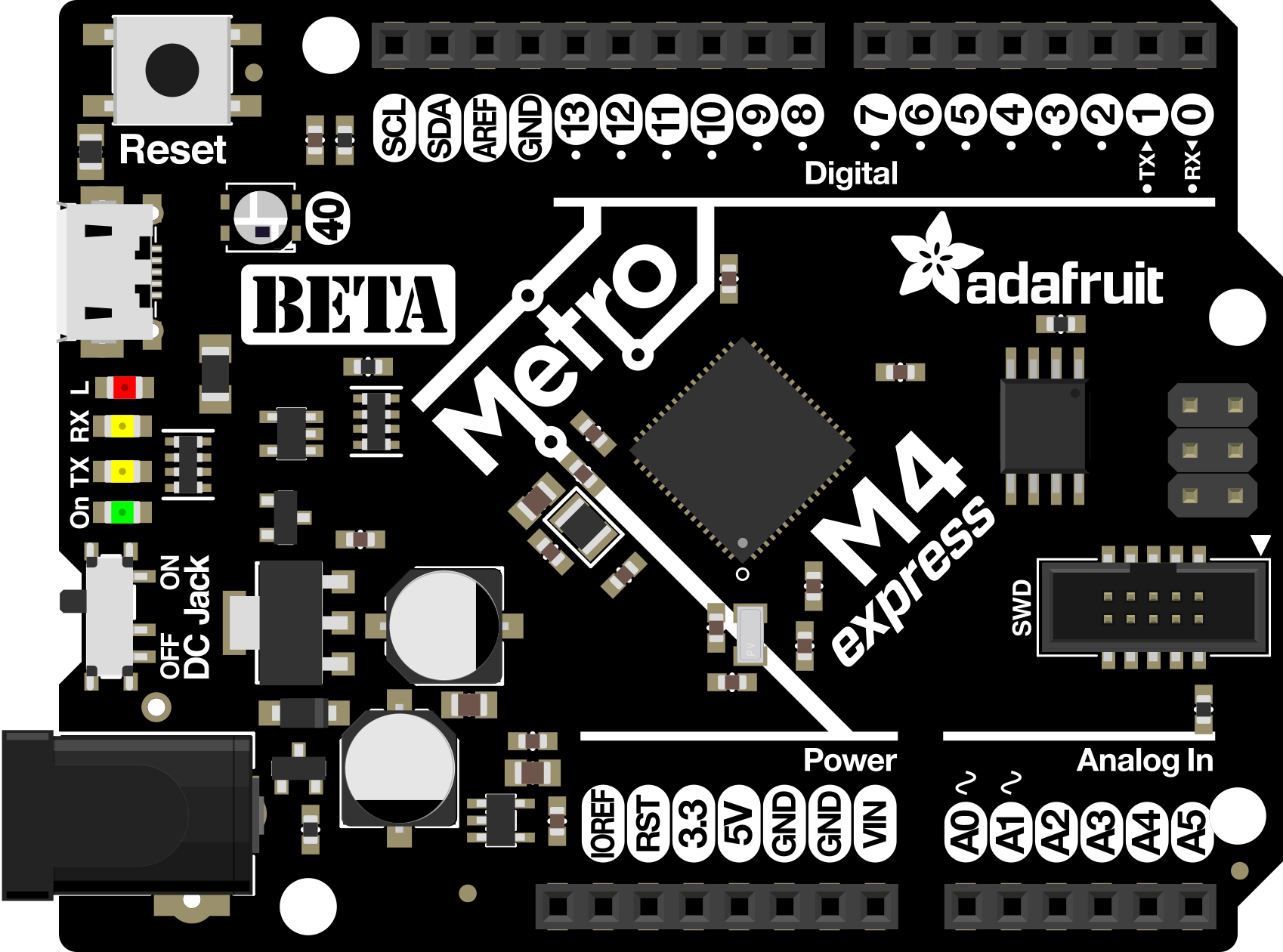
 Design with Adafruit Metro M4 Express in Cirkit Designer
Introduction
The Adafruit Metro M4 Express (Manufacturer Part ID: 3382) is a powerful microcontroller board designed for advanced electronics projects. It is based on the Atmel SAMD51 microcontroller, featuring a 120 MHz ARM Cortex-M4 processor with floating-point support, 512 KB of RAM, and 4 MB of onboard flash storage. This board is compatible with both CircuitPython and Arduino IDE, making it versatile for a wide range of applications.
Explore Projects Built with Adafruit Metro M4 Express
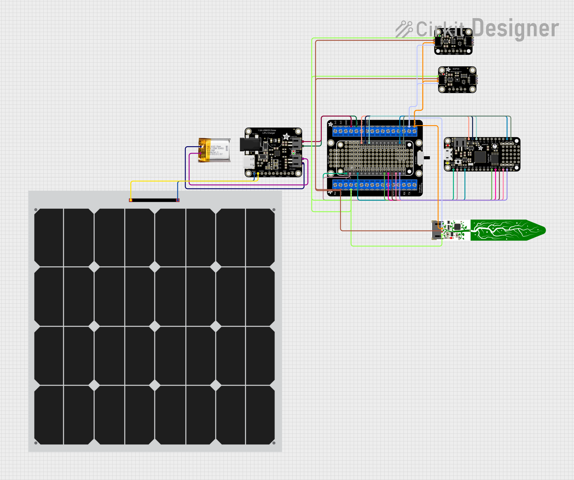 Open Project in Cirkit Designer
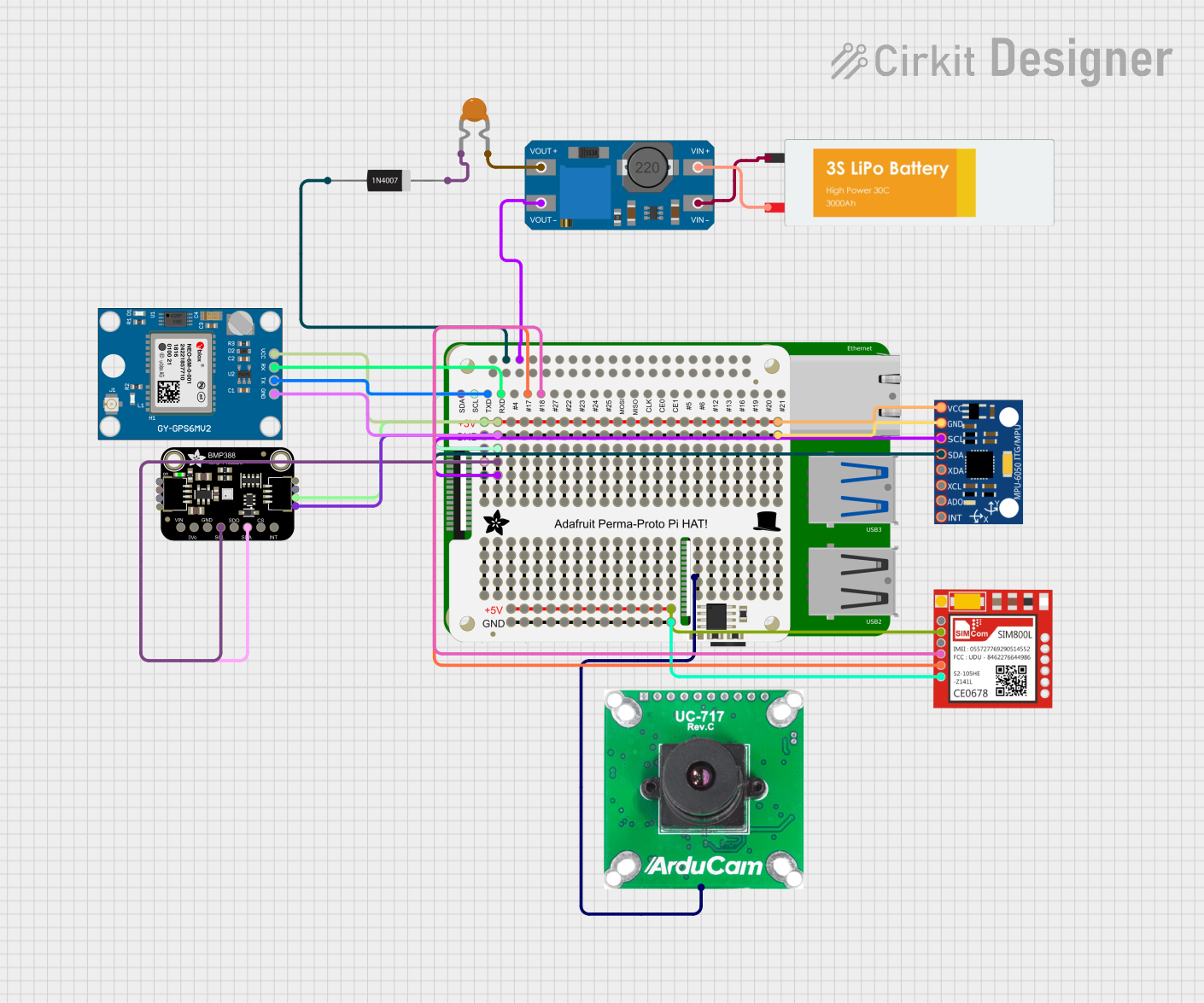 Open Project in Cirkit Designer
 Open Project in Cirkit Designer
 Open Project in Cirkit Designer
Explore Projects Built with Adafruit Metro M4 Express
Open Project in Cirkit DesignerOpen Project in Cirkit DesignerOpen Project in Cirkit DesignerOpen Project in Cirkit DesignerCommon Applications and Use Cases
- Robotics and automation systems
- Data logging and IoT (Internet of Things) devices
- Audio processing and DSP (Digital Signal Processing)
- Educational projects and prototyping
- High-performance embedded systems
Technical Specifications
The Adafruit Metro M4 Express is packed with features that make it suitable for demanding applications. Below are its key technical details:
Key Technical Details
| Specification | Value |
|---|---|
| Microcontroller | Atmel SAMD51 (ARM Cortex-M4, 120 MHz) |
| RAM | 512 KB |
| Flash Storage | 4 MB onboard QSPI |
| Operating Voltage | 3.3 V |
| Input Voltage (VIN) | 6-12 V |
| Digital I/O Pins | 25 (with 12 PWM outputs) |
| Analog Input Pins | 6 (12-bit ADC) |
| Analog Output Pins | 1 (10-bit DAC) |
| Communication Interfaces | UART, I2C, SPI, CAN, USB |
| USB Support | USB-C (with native USB support) |
| CircuitPython Compatibility | Yes |
| Arduino IDE Compatibility | Yes |
| Dimensions | 71.1 mm x 53.3 mm |
Pin Configuration and Descriptions
The Adafruit Metro M4 Express features a standard Arduino-compatible pinout. Below is a detailed description of its pins:
| Pin Name | Type | Description |
|---|---|---|
| VIN | Power Input | External power input (6-12 V) |
| 3.3V | Power Output | Regulated 3.3 V output |
| GND | Ground | Ground connection |
| A0-A5 | Analog Input | 12-bit ADC pins for analog signals |
| D0-D13 | Digital I/O | General-purpose digital I/O pins |
| PWM Pins | Digital I/O | D2, D3, D5, D6, D9, D10, D11 (PWM capable) |
| SDA | I2C Data | I2C data line |
| SCL | I2C Clock | I2C clock line |
| TX | UART TX | UART transmit line |
| RX | UART RX | UART receive line |
| DAC0 | Analog Output | 10-bit DAC for analog signal generation |
| USB-C | USB Interface | USB-C port for programming and power |
| RESET | Reset | Resets the microcontroller |
Usage Instructions
How to Use the Component in a Circuit
Powering the Board:
- Connect the board to a computer or USB power source using the USB-C port.
- Alternatively, supply 6-12 V to the VIN pin for external power.
Programming the Board:
- Install the required drivers and software for CircuitPython or Arduino IDE.
- For Arduino IDE, install the Adafruit SAMD Boards package via the Board Manager.
- For CircuitPython, copy the CircuitPython firmware to the board's USB drive.
Connecting Peripherals:
- Use the digital and analog pins to connect sensors, actuators, and other peripherals.
- For I2C devices, connect to the SDA and SCL pins.
- For SPI devices, use the MOSI, MISO, and SCK pins.
Uploading Code:
- In Arduino IDE, select "Adafruit Metro M4 Express" as the board and upload your sketch.
- For CircuitPython, save your Python script as
code.pyon the board's USB drive.
Important Considerations and Best Practices
- Voltage Levels: The board operates at 3.3 V logic levels. Ensure connected peripherals are compatible with 3.3 V to avoid damage.
- Power Supply: When using VIN, ensure the input voltage is within the 6-12 V range.
- Heat Management: The SAMD51 processor can get warm during intensive tasks. Ensure proper ventilation if running the board at high loads.
- Firmware Updates: Regularly check for firmware updates from Adafruit to ensure compatibility and access to new features.
Example Code for Arduino IDE
Below is an example of how to blink an LED connected to pin D13:
// Blink an LED on pin D13
void setup() {
  pinMode(13, OUTPUT); // Set pin D13 as an output
}

void loop() {
  digitalWrite(13, HIGH); // Turn the LED on
  delay(1000);            // Wait for 1 second
  digitalWrite(13, LOW);  // Turn the LED off
  delay(1000);            // Wait for 1 second
}
Example Code for CircuitPython
Below is an example of how to blink the onboard LED using CircuitPython:
import board
import digitalio
import time
Configure the onboard LED (connected to D13)
led = digitalio.DigitalInOut(board.D13) led.direction = digitalio.Direction.OUTPUT
while True: led.value = True # Turn the LED on time.sleep(1) # Wait for 1 second led.value = False # Turn the LED off time.sleep(1) # Wait for 1 second
Troubleshooting and FAQs
Common Issues and Solutions
Board Not Recognized by Computer:
- Ensure the USB-C cable is data-capable (not just for charging).
- Check that the board is in bootloader mode by double-pressing the reset button.
Code Not Running:
- Verify that the correct board is selected in the Arduino IDE.
- For CircuitPython, ensure the script is named
code.pyand placed in the root directory.
Peripheral Not Responding:
- Double-check wiring and ensure the peripheral operates at 3.3 V logic levels.
- Verify that the correct pins are used in the code.
Overheating:
- Avoid running the board at maximum load for extended periods without proper ventilation.
- Check for short circuits or excessive current draw from connected peripherals.
FAQs
Q: Can I use 5 V peripherals with the Metro M4 Express?
A: No, the Metro M4 Express operates at 3.3 V logic levels. Use a level shifter for 5 V peripherals.
Q: How do I reset the board to factory settings?
A: Double-press the reset button to enter bootloader mode, then reflash the firmware.
Q: Is the Metro M4 Express compatible with Arduino shields?
A: Yes, it has an Arduino-compatible pinout, but ensure the shield operates at 3.3 V.
Q: Can I use the Metro M4 Express for machine learning applications?
A: Yes, the SAMD51's powerful processor and floating-point support make it suitable for lightweight ML tasks.
Q: Where can I find additional libraries and examples?
A: Visit the Adafruit Metro M4 Express product page for libraries, tutorials, and resources.