How to Use Switch Symbol SPST: Examples, Pinouts, and Specs

Introduction
A Single Pole Single Throw (SPST) switch is a fundamental electronic component used to control the flow of current in a circuit. It operates as a simple on/off switch, with two terminals that either connect or disconnect a single circuit. When the switch is closed, it allows current to flow; when open, it interrupts the flow.
Explore Projects Built with Switch Symbol SPST
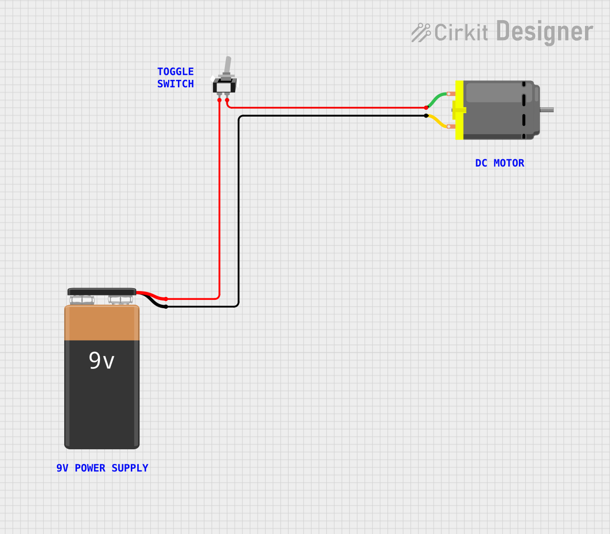


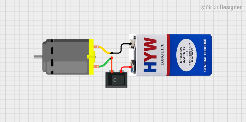
Explore Projects Built with Switch Symbol SPST
Common Applications and Use Cases
- Power control for small electronic devices
- Light switches in household circuits
- Circuit testing and debugging
- Basic on/off control in DIY electronics projects
- Used in conjunction with microcontrollers like Arduino for input control
Technical Specifications
Below are the key technical details of a typical SPST switch:
| Parameter | Value |
|---|---|
| Type | Single Pole Single Throw (SPST) |
| Number of Terminals | 2 |
| Voltage Rating | Typically 3V to 250V (varies by model) |
| Current Rating | Typically 0.5A to 15A (varies by model) |
| Contact Resistance | < 50 mΩ |
| Insulation Resistance | > 100 MΩ |
| Mechanical Life | 10,000 to 100,000 operations |
Pin Configuration and Descriptions
The SPST switch has two terminals, as described below:
| Pin | Description |
|---|---|
| Pin 1 | Connects to one side of the circuit (input) |
| Pin 2 | Connects to the other side of the circuit (output) |
Usage Instructions
How to Use the SPST Switch in a Circuit
- Identify the Terminals: Locate the two terminals of the SPST switch. These are typically labeled or easily identifiable.
- Connect the Circuit:
- Connect one terminal (Pin 1) to the power source or signal input.
- Connect the other terminal (Pin 2) to the load or circuit output.
- Operation: Toggle the switch to open or close the circuit. When the switch is closed, current flows; when open, the circuit is interrupted.
Important Considerations and Best Practices
- Voltage and Current Ratings: Ensure the switch's voltage and current ratings are suitable for your application to avoid damage or failure.
- Debouncing: When used with microcontrollers, consider implementing software or hardware debouncing to handle switch bounce (rapid on/off toggling due to mechanical contacts).
- Mounting: Secure the switch properly to avoid accidental disconnections or damage.
- Safety: Always disconnect power before wiring or modifying the circuit to prevent electric shock or short circuits.
Example: Using an SPST Switch with Arduino UNO
Below is an example of how to use an SPST switch as an input to an Arduino UNO:
// Example: Reading the state of an SPST switch with Arduino UNO

const int switchPin = 2;  // Pin connected to one terminal of the SPST switch
const int ledPin = 13;    // Built-in LED pin on Arduino UNO

void setup() {
  pinMode(switchPin, INPUT_PULLUP); // Configure switch pin as input with pull-up resistor
  pinMode(ledPin, OUTPUT);          // Configure LED pin as output
}

void loop() {
  int switchState = digitalRead(switchPin); // Read the state of the switch

  if (switchState == LOW) {
    // If the switch is closed (connected to ground), turn on the LED
    digitalWrite(ledPin, HIGH);
  } else {
    // If the switch is open, turn off the LED
    digitalWrite(ledPin, LOW);
  }
}
Notes:
- The
INPUT_PULLUPmode enables the internal pull-up resistor, simplifying the circuit by eliminating the need for an external resistor. - The switch should connect Pin 2 to ground when closed.
Troubleshooting and FAQs
Common Issues and Solutions
Switch Not Working:
- Cause: Loose or incorrect wiring.
- Solution: Double-check the connections and ensure the switch terminals are properly connected to the circuit.
Switch Bouncing:
- Cause: Mechanical contacts in the switch may cause rapid on/off toggling.
- Solution: Implement software debouncing in your code or use a capacitor for hardware debouncing.
Overheating or Damage:
- Cause: Exceeding the voltage or current rating of the switch.
- Solution: Verify the ratings of the switch and ensure they match the circuit requirements.
No Response in Arduino Circuit:
- Cause: Incorrect pin configuration or missing pull-up resistor.
- Solution: Ensure the correct pin is used in the code and enable the internal pull-up resistor.
FAQs
Q: Can I use an SPST switch to control AC devices?
A: Yes, but ensure the switch is rated for the voltage and current of the AC device. Use caution when working with high voltages.
Q: How do I debounce an SPST switch in software?
A: You can use a delay or a state-checking algorithm in your code to filter out rapid toggling caused by mechanical bouncing.
Q: Can I use an SPST switch with a breadboard?
A: Yes, SPST switches are commonly used with breadboards for prototyping. Ensure the switch fits securely into the breadboard holes.
Q: What is the difference between SPST and SPDT switches?
A: An SPST switch controls a single circuit with two terminals, while an SPDT (Single Pole Double Throw) switch has three terminals and can toggle between two circuits.
This concludes the documentation for the SPST switch.