Cirkit Designer Logo
Cirkit Designer
Your all-in-one circuit design IDE
Home / 
Component Documentation

How to Use CJMCU-6035: Examples, Pinouts, and Specs

Image of CJMCU-6035
Cirkit Designer LogoDesign with CJMCU-6035 in Cirkit Designer

Introduction

The CJMCU-6035, manufactured by UHXRUY, is a high-performance sensor module that integrates a high-precision 3-axis accelerometer and gyroscope. This module is designed for motion detection, orientation sensing, and environmental monitoring. It is widely used in applications such as robotics, drones, smartphones, and other devices requiring accurate motion tracking and orientation data.

The CJMCU-6035 is based on the VEML6035 Ambient Light Sensor, which provides precise light intensity measurements. It is ideal for applications requiring ambient light sensing, such as automatic brightness adjustment in displays, smart lighting systems, and environmental monitoring.

Explore Projects Built with CJMCU-6035

Use Cirkit Designer to design, explore, and prototype these projects online. Some projects support real-time simulation. Click "Open Project" to start designing instantly!
Arduino Nano-Based Wireless Joystick and Motion Controller
Image of hand gesture: A project utilizing CJMCU-6035 in a practical application
This circuit features an Arduino Nano microcontroller interfaced with an HC-05 Bluetooth module, an MPU-6050 accelerometer/gyroscope, and a KY-023 Dual Axis Joystick Module. The Arduino Nano is powered by a 9V battery through a rocker switch and communicates with the HC-05 for Bluetooth connectivity, reads joystick positions from the KY-023 module via analog inputs, and communicates with the MPU-6050 over I2C to capture motion data. The circuit is likely designed for wireless control and motion sensing applications, such as a remote-controlled robot or a game controller.
Cirkit Designer LogoOpen Project in Cirkit Designer
Battery-Powered Emergency Alert System with NUCLEO-F072RB, SIM800L, and GPS NEO 6M
Image of women safety: A project utilizing CJMCU-6035 in a practical application
This circuit is an emergency alert system that uses a NUCLEO-F072RB microcontroller to send SMS alerts and make calls via a SIM800L GSM module, while obtaining location data from a GPS NEO 6M module. The system is powered by a Li-ion battery and includes a TP4056 module for battery charging and protection, with a rocker switch to control power to the microcontroller.
Cirkit Designer LogoOpen Project in Cirkit Designer
Arduino Mega 2560 Based Security System with Fingerprint Authentication and SMS Alerts
Image of Door security system: A project utilizing CJMCU-6035 in a practical application
This circuit features an Arduino Mega 2560 microcontroller interfaced with a SIM800L GSM module, two fingerprint scanners, an I2C LCD display, an IR sensor, and a piezo buzzer. Power management is handled by a PowerBoost 1000 Basic Pad USB, a TP4056 charging module, and a Li-ion 18650 battery, with an option to use a Mini AC-DC 110V-230V to 5V 700mA module for direct power supply. The primary functionality appears to be a security system with GSM communication capabilities, biometric access control, and visual/audible feedback.
Cirkit Designer LogoOpen Project in Cirkit Designer
ESP8266 and SIM800L Based GPS Tracker with I2C LCD Display and Battery Power
Image of Little Innovator Competition: A project utilizing CJMCU-6035 in a practical application
This circuit integrates an ESP8266 NodeMCU microcontroller with a SIM800L GSM module, a GPS NEO 6M module, and a 16x2 I2C LCD display for communication and location tracking. It also includes a pushbutton for user input, a piezo buzzer for audio alerts, and is powered by a 2x 18650 battery pack through an LM2596 step-down module.
Cirkit Designer LogoOpen Project in Cirkit Designer

Explore Projects Built with CJMCU-6035

Use Cirkit Designer to design, explore, and prototype these projects online. Some projects support real-time simulation. Click "Open Project" to start designing instantly!
Image of hand gesture: A project utilizing CJMCU-6035 in a practical application
Arduino Nano-Based Wireless Joystick and Motion Controller
This circuit features an Arduino Nano microcontroller interfaced with an HC-05 Bluetooth module, an MPU-6050 accelerometer/gyroscope, and a KY-023 Dual Axis Joystick Module. The Arduino Nano is powered by a 9V battery through a rocker switch and communicates with the HC-05 for Bluetooth connectivity, reads joystick positions from the KY-023 module via analog inputs, and communicates with the MPU-6050 over I2C to capture motion data. The circuit is likely designed for wireless control and motion sensing applications, such as a remote-controlled robot or a game controller.
Cirkit Designer LogoOpen Project in Cirkit Designer
Image of women safety: A project utilizing CJMCU-6035 in a practical application
Battery-Powered Emergency Alert System with NUCLEO-F072RB, SIM800L, and GPS NEO 6M
This circuit is an emergency alert system that uses a NUCLEO-F072RB microcontroller to send SMS alerts and make calls via a SIM800L GSM module, while obtaining location data from a GPS NEO 6M module. The system is powered by a Li-ion battery and includes a TP4056 module for battery charging and protection, with a rocker switch to control power to the microcontroller.
Cirkit Designer LogoOpen Project in Cirkit Designer
Image of Door security system: A project utilizing CJMCU-6035 in a practical application
Arduino Mega 2560 Based Security System with Fingerprint Authentication and SMS Alerts
This circuit features an Arduino Mega 2560 microcontroller interfaced with a SIM800L GSM module, two fingerprint scanners, an I2C LCD display, an IR sensor, and a piezo buzzer. Power management is handled by a PowerBoost 1000 Basic Pad USB, a TP4056 charging module, and a Li-ion 18650 battery, with an option to use a Mini AC-DC 110V-230V to 5V 700mA module for direct power supply. The primary functionality appears to be a security system with GSM communication capabilities, biometric access control, and visual/audible feedback.
Cirkit Designer LogoOpen Project in Cirkit Designer
Image of Little Innovator Competition: A project utilizing CJMCU-6035 in a practical application
ESP8266 and SIM800L Based GPS Tracker with I2C LCD Display and Battery Power
This circuit integrates an ESP8266 NodeMCU microcontroller with a SIM800L GSM module, a GPS NEO 6M module, and a 16x2 I2C LCD display for communication and location tracking. It also includes a pushbutton for user input, a piezo buzzer for audio alerts, and is powered by a 2x 18650 battery pack through an LM2596 step-down module.
Cirkit Designer LogoOpen Project in Cirkit Designer

Technical Specifications

Key Technical Details

  • Manufacturer: UHXRUY
  • Part ID: CJMCU-6035 VEML6035
  • Sensor Type: Ambient Light Sensor with integrated 3-axis accelerometer and gyroscope
  • Supply Voltage: 2.5V to 3.6V
  • Communication Interface: I2C (Inter-Integrated Circuit)
  • I2C Address: 0x10 (default)
  • Operating Temperature Range: -40°C to +85°C
  • Light Sensitivity Range: 0.0036 lux to 18.45 klux
  • Accelerometer Range: ±2g, ±4g, ±8g, ±16g (configurable)
  • Gyroscope Range: ±125°/s, ±250°/s, ±500°/s, ±1000°/s, ±2000°/s (configurable)
  • Power Consumption: Low power mode available for energy-efficient applications

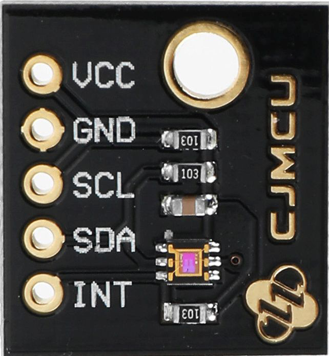
Pin Configuration and Descriptions

The CJMCU-6035 module has the following pinout:

Pin Name Description
1 VCC Power supply input (2.5V to 3.6V)
2 GND Ground
3 SDA I2C data line
4 SCL I2C clock line
5 INT Interrupt output (motion detection)
6 NC Not connected (leave unconnected)

Usage Instructions

How to Use the Component in a Circuit

  1. Power Supply: Connect the VCC pin to a 3.3V power source and the GND pin to ground. Ensure the power supply is stable and within the specified voltage range.
  2. I2C Communication: Connect the SDA and SCL pins to the corresponding I2C pins on your microcontroller. Use pull-up resistors (typically 4.7kΩ) on the SDA and SCL lines if not already present on the module.
  3. Interrupt Pin: Optionally, connect the INT pin to a GPIO pin on your microcontroller to handle motion detection or light threshold interrupts.
  4. Configuration: Use I2C commands to configure the sensor's operating modes, sensitivity, and thresholds as required for your application.

Important Considerations and Best Practices

  • I2C Address Conflicts: Ensure no other devices on the I2C bus share the same address (0x10). If conflicts occur, consider using an I2C multiplexer.
  • Ambient Light Calibration: Calibrate the sensor for your specific environment to improve accuracy.
  • Motion Sensitivity: Adjust the accelerometer and gyroscope ranges based on the expected motion dynamics of your application.
  • Power Management: Use the low-power mode to conserve energy in battery-powered applications.

Example Code for Arduino UNO

Below is an example Arduino sketch to read ambient light data from the CJMCU-6035:

#include <Wire.h>

// I2C address of the CJMCU-6035
#define CJMCU_6035_ADDR 0x10

void setup() {
  Wire.begin(); // Initialize I2C communication
  Serial.begin(9600); // Initialize serial communication for debugging

  // Configure the sensor (example: set gain and integration time)
  Wire.beginTransmission(CJMCU_6035_ADDR);
  Wire.write(0x00); // Command register
  Wire.write(0x01); // Example configuration value
  Wire.endTransmission();

  Serial.println("CJMCU-6035 initialized.");
}

void loop() {
  uint16_t lightData = 0;

  // Request 2 bytes of light data from the sensor
  Wire.beginTransmission(CJMCU_6035_ADDR);
  Wire.write(0x04); // Data register
  Wire.endTransmission();
  Wire.requestFrom(CJMCU_6035_ADDR, 2);

  if (Wire.available() == 2) {
    lightData = Wire.read(); // Read high byte
    lightData = (lightData << 8) | Wire.read(); // Read low byte
  }

  // Print the light intensity in lux
  Serial.print("Ambient Light: ");
  Serial.print(lightData * 0.0036); // Convert to lux
  Serial.println(" lux");

  delay(1000); // Wait 1 second before the next reading
}

Troubleshooting and FAQs

Common Issues and Solutions

  1. No Data from Sensor:

    • Ensure the I2C connections (SDA, SCL) are correct and secure.
    • Verify the I2C address (0x10) matches the sensor's default address.
    • Check for proper pull-up resistors on the I2C lines.
  2. Incorrect Light Readings:

    • Calibrate the sensor for your specific environment.
    • Avoid placing the sensor in direct sunlight or near reflective surfaces.
  3. Interrupt Pin Not Working:

    • Ensure the INT pin is connected to a GPIO pin configured as an input.
    • Verify the interrupt threshold settings via I2C commands.
  4. Power Issues:

    • Confirm the power supply voltage is within the 2.5V to 3.6V range.
    • Check for noise or instability in the power supply.

FAQs

  • Can the CJMCU-6035 be used with 5V microcontrollers?
    Yes, but you must use a level shifter for the I2C lines to avoid damaging the sensor.

  • What is the maximum I2C clock speed supported?
    The CJMCU-6035 supports I2C clock speeds up to 400kHz (Fast Mode).

  • How do I change the accelerometer or gyroscope range?
    Use the appropriate I2C commands to configure the desired range. Refer to the sensor's datasheet for details.

  • Can the sensor operate in low-light conditions?
    Yes, the sensor is highly sensitive and can measure light intensities as low as 0.0036 lux.